Manual
Page 1
GA-M61PME-S2P AM2+/AM2 socket motherboard for AMD PhenomTM FX processor/AMD PhenomTM X4 processor/ AMD PhenomTM X3 processor/AMD AthlonTM X2 processor/ AMD AthlonTM processor/AMD SempronTM X2 processor/ AMD SempronTM processor User's Manual Rev. 1002 12ME-M61PMEP2-1002R
GA-M61PME-S2P AM2+/AM2 socket motherboard for AMD PhenomTM FX processor/AMD PhenomTM X4 processor/ AMD PhenomTM X3 processor/AMD AthlonTM X2 processor/ AMD AthlonTM processor/AMD SempronTM X2 processor/ AMD SempronTM processor User's Manual Rev. 1002 12ME-M61PMEP2-1002R
Manual
Page 2
Motherboard GA-M61PME-S2P Jan. 8, 2009 Motherboard GA-M61PME-S2P Jan. 8, 2009 -2-
Motherboard GA-M61PME-S2P Jan. 8, 2009 Motherboard GA-M61PME-S2P Jan. 8, 2009 -2-
Manual
Page 4
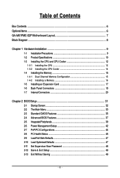
Table of Contents Box Contents ...6 OptionalItems ...6 GA-M61PME-S2P Motherboard Layout 7 Block Diagram ...8 Chapter 1 Hardware Installation 9 1-1 Installation Precautions 9 1-2 Product Specifications 10 1-3 Installing the CPU and CPU Cooler 12 1-3-1 Installing the CPU 12 1-3-2 Installing the ...
Table of Contents Box Contents ...6 OptionalItems ...6 GA-M61PME-S2P Motherboard Layout 7 Block Diagram ...8 Chapter 1 Hardware Installation 9 1-1 Installation Precautions 9 1-2 Product Specifications 10 1-3 Installing the CPU and CPU Cooler 12 1-3-1 Installing the CPU 12 1-3-2 Installing the ...
Manual
Page 6
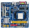
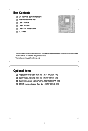
Box Contents GA-M61PME-S2P motherboard Motherboard driver disk User's Manual One IDE cable One SATA 3Gb/s cables I/O Shield • The box contents above are subject to change without notice. • The motherboard image is for reference only and the actual items shall depend on product package you obtain. Optional Items Floppy disk drive cable (Part No. 12CF1-1FD001-7*R) 2-port USB 2.0 bracket (Part No. 12CR1-1UB030-5*R) 2-port SATA power cable (Part No. 12CF1-2SERPW-0*R) S/PDIF in and out cable (Part No. 12CR1-1SPINO-1*R) - 6 - The box contents are for reference only.
Box Contents GA-M61PME-S2P motherboard Motherboard driver disk User's Manual One IDE cable One SATA 3Gb/s cables I/O Shield • The box contents above are subject to change without notice. • The motherboard image is for reference only and the actual items shall depend on product package you obtain. Optional Items Floppy disk drive cable (Part No. 12CF1-1FD001-7*R) 2-port USB 2.0 bracket (Part No. 12CR1-1UB030-5*R) 2-port SATA power cable (Part No. 12CF1-2SERPW-0*R) S/PDIF in and out cable (Part No. 12CR1-1SPINO-1*R) - 6 - The box contents are for reference only.
Manual
Page 10
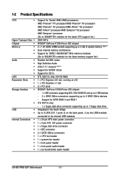
...processor/AMD AthlonTM X2 processor/ AMD AthlonTM processor/AMD SempronTM X2 processor/ AMD SempronTM processor (Go to GIGABYTE's website for the latest CPU support list.) 2000 MT/s NVIDIA® GeForce 6100/nForce 430 chipset 2... (Note 1) Dual channel memory architecture Support for DDR2 1066/800/667 MHz memory modules (Go to GIGABYTE's website for the latest memory support list.) Realtek ALC883 codec High Definition Audio 2/4/5.1/7.1-channel (Note 2) Support...system fan header 1 x front panel header 1 x front panel audio header 1 x surround/center audio header GA-M61PME-S2P Motherboard - 10 -
...processor/AMD AthlonTM X2 processor/ AMD AthlonTM processor/AMD SempronTM X2 processor/ AMD SempronTM processor (Go to GIGABYTE's website for the latest CPU support list.) 2000 MT/s NVIDIA® GeForce 6100/nForce 430 chipset 2... (Note 1) Dual channel memory architecture Support for DDR2 1066/800/667 MHz memory modules (Go to GIGABYTE's website for the latest memory support list.) Realtek ALC883 codec High Definition Audio 2/4/5.1/7.1-channel (Note 2) Support...system fan header 1 x front panel header 1 x front panel audio header 1 x surround/center audio header GA-M61PME-S2P Motherboard - 10 -
Manual
Page 12
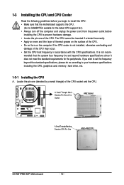
... of the CPU socket and the CPU. A Small Triangle Mark Denotes Pin One of the CPU. mended that the motherboard supports the CPU. (Go to GIGABYTE's website for the peripherals. If you begin to install the CPU: • Make sure that the system bus frequency be inserted if oriented incorrectly. •... in accordance with the CPU specifications. Locate the pin one of the Socket AM2 Socket A Small Triangle Marking Denotes CPU Pin One AM2+/AM2 CPU GA-M61PME-S2P Motherboard - 12 -
... of the CPU socket and the CPU. A Small Triangle Mark Denotes Pin One of the CPU. mended that the motherboard supports the CPU. (Go to GIGABYTE's website for the peripherals. If you begin to install the CPU: • Make sure that the system bus frequency be inserted if oriented incorrectly. •... in accordance with the CPU specifications. Locate the pin one of the Socket AM2 Socket A Small Triangle Marking Denotes CPU Pin One AM2+/AM2 CPU GA-M61PME-S2P Motherboard - 12 -
Manual
Page 14
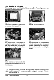
1-3-2 Installing the CPU Cooler Follow the steps below to correctly install the CPU cooler on the CPU. (The following procedure uses the GIGABYTE cooler as the picture above shows) to lock into place. (Refer to your CPU cooler installation manual for instructions on installing the cooler.) Step 5:... the CPU. Use extreme care when removing the CPU cooler because the thermal grease/tape between the CPU cooler and CPU may damage the CPU. GA-M61PME-S2P Motherboard - 14 - Step 4: Turn the cam handle from the left side to the right side (as the example.) Step 1: Apply an even and ...
1-3-2 Installing the CPU Cooler Follow the steps below to correctly install the CPU cooler on the CPU. (The following procedure uses the GIGABYTE cooler as the picture above shows) to lock into place. (Refer to your CPU cooler installation manual for instructions on installing the cooler.) Step 5:... the CPU. Use extreme care when removing the CPU cooler because the thermal grease/tape between the CPU cooler and CPU may damage the CPU. GA-M61PME-S2P Motherboard - 14 - Step 4: Turn the cam handle from the left side to the right side (as the example.) Step 1: Apply an even and ...
Manual
Page 16
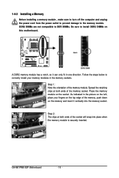
Follow the steps below to correctly install your fingers on the top edge of the socket will snap into the memory socket. GA-M61PME-S2P Motherboard - 16 - Place the memory module on this motherboard. As indicated in the picture on the left, place your memory modules in one direction. Notch ...
Follow the steps below to correctly install your fingers on the top edge of the socket will snap into the memory socket. GA-M61PME-S2P Motherboard - 16 - Place the memory module on this motherboard. As indicated in the picture on the left, place your memory modules in one direction. Notch ...
Manual
Page 18
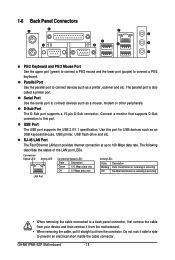
... Mbps data rate Activity LED: State Description Blinking Data transmission or receiving is occurring Off No data transmission or receiving is also called a printer port. GA-M61PME-S2P Motherboard - 18 - The parallel port is occurring LAN Port • When removing the cable connected to connect a PS/2 keyboard. USB Port The USB port supports...
... Mbps data rate Activity LED: State Description Blinking Data transmission or receiving is occurring Off No data transmission or receiving is also called a printer port. GA-M61PME-S2P Motherboard - 18 - The parallel port is occurring LAN Port • When removing the cable connected to connect a PS/2 keyboard. USB Port The USB port supports...
Manual
Page 20
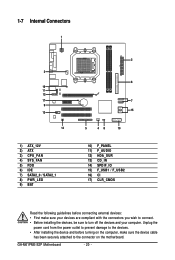
... and your devices are compliant with the connectors you wish to connect. • Before installing the devices, be sure to the connector on the motherboard. GA-M61PME-S2P Motherboard - 20 - 1-7 Internal Connectors 1 3 16 11 12 17 9 13 14 1) ATX_12V 2) ATX 3) CPU_FAN 4) SYS_FAN 5) FDD 6) IDE 7) SATA2_0 / SATA2_1 8) PWR_LED 9) BAT 2 6 7 15 5 48 10 10) F_PANEL...
... and your devices are compliant with the connectors you wish to connect. • Before installing the devices, be sure to the connector on the motherboard. GA-M61PME-S2P Motherboard - 20 - 1-7 Internal Connectors 1 3 16 11 12 17 9 13 14 1) ATX_12V 2) ATX 3) CPU_FAN 4) SYS_FAN 5) FDD 6) IDE 7) SATA2_0 / SATA2_1 8) PWR_LED 9) BAT 2 6 7 15 5 48 10 10) F_PANEL...
Manual
Page 22
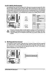
Overheating may result in the correct orientation (the black connector wire is typically designated by a stripe of different color. 33 1 34 2 GA-M61PME-S2P Motherboard - 22 - Before connecting a floppy disk drive, be sure to connect it is used to prevent your CPU and system from overheating. The motherboard supports ...
Overheating may result in the correct orientation (the black connector wire is typically designated by a stripe of different color. 33 1 34 2 GA-M61PME-S2P Motherboard - 22 - Before connecting a floppy disk drive, be sure to connect it is used to prevent your CPU and system from overheating. The motherboard supports ...
Manual
Page 24
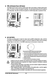
... S0 On S1 Blinking S3/S4/S5 Off 9) BAT (BATTERY) The battery provides power to replace the battery by removing the battery: 1. Replace the battery. 4. GA-M61PME-S2P Motherboard - 24 - The LED keeps blinking when the system is in accordance with an incorrect model. • Contact the place of the battery (the positive...
... S0 On S1 Blinking S3/S4/S5 Off 9) BAT (BATTERY) The battery provides power to replace the battery by removing the battery: 1. Replace the battery. 4. GA-M61PME-S2P Motherboard - 24 - The LED keeps blinking when the system is in accordance with an incorrect model. • Contact the place of the battery (the positive...
Manual
Page 26
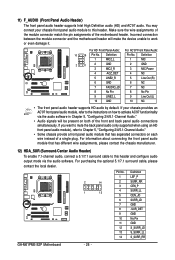
.... 2 14 1 13 Pin No. 1 2 3 4 5 6 7 8 9 10 11 12 13 14 Definition LEF_P SURR_RR CEN_P SURR_LL CEN_JD SURR_JD GND -SUR_DET GND No Pin GND S_SURR_JD S_SURR_LL S_SURR_RR GA-M61PME-S2P Motherboard - 26 - For HD Front Panel Audio: For AC'97 Front Panel Audio: 10 9 Pin No.
.... 2 14 1 13 Pin No. 1 2 3 4 5 6 7 8 9 10 11 12 13 14 Definition LEF_P SURR_RR CEN_P SURR_LL CEN_JD SURR_JD GND -SUR_DET GND No Pin GND S_SURR_JD S_SURR_LL S_SURR_RR GA-M61PME-S2P Motherboard - 26 - For HD Front Panel Audio: For AC'97 Front Panel Audio: 10 9 Pin No.
Manual
Page 28
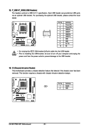
Pin No. Definition 1 1 Signal 2 GND GA-M61PME-S2P Motherboard - 28 - For purchasing the optional USB bracket, please contact the local dealer. 2 10 1 9 Pin No. 1 2 3 4 5 6 7 8 9 10 Definition Power (5V) Power (5V) USB DXUSB DYUSB ...
Pin No. Definition 1 1 Signal 2 GND GA-M61PME-S2P Motherboard - 28 - For purchasing the optional USB bracket, please contact the local dealer. 2 10 1 9 Pin No. 1 2 3 4 5 6 7 8 9 10 Definition Power (5V) Power (5V) USB DXUSB DYUSB ...

Manual
Page 30
GA-M61PME-S2P Motherboard - 30 -
GA-M61PME-S2P Motherboard - 30 -
Manual
Page 32
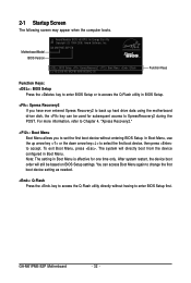
...as needed. : Q-Flash Press the key to access the Q-Flash utility directly without entering BIOS Setup. To exit Boot Menu, press . GA-M61PME-S2P Motherboard - 32 - After system restart, the device boot order will directly boot from the device configured in Boot Menu is effective for ...be based on BIOS Setup settings. Motherboard Model BIOS Version Award Modular BIOS v6.00PG, An Energy Star Ally Copyright (C) 1984-2008, Award Software, Inc. GA-M61PME-S2P E8 . . . . : BIOS Setup : XpressRecovery2 : Boot Menu : Qflash 12/16/2008-NV-MCP61-6A61KG0AC-00 Function Keys Function Keys: : ...
...as needed. : Q-Flash Press the key to access the Q-Flash utility directly without entering BIOS Setup. To exit Boot Menu, press . GA-M61PME-S2P Motherboard - 32 - After system restart, the device boot order will directly boot from the device configured in Boot Menu is effective for ...be based on BIOS Setup settings. Motherboard Model BIOS Version Award Modular BIOS v6.00PG, An Energy Star Ally Copyright (C) 1984-2008, Award Software, Inc. GA-M61PME-S2P E8 . . . . : BIOS Setup : XpressRecovery2 : Boot Menu : Qflash 12/16/2008-NV-MCP61-6A61KG0AC-00 Function Keys Function Keys: : ...
Manual
Page 34
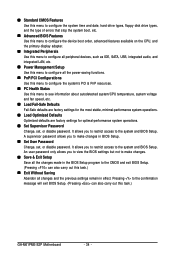
... Setup. It allows you to view the BIOS settings but not to configure the system's PCI & PnP resources. PC Health Status Use this task.) GA-M61PME-S2P Motherboard - 34 -
... Setup. It allows you to view the BIOS settings but not to configure the system's PCI & PnP resources. PC Health Status Use this task.) GA-M61PME-S2P Motherboard - 34 -
Manual
Page 36
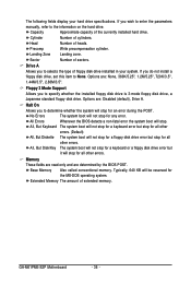
... conventional memory. Cylinder Number of extended memory. Floppy 3 Mode Support Allows you to the information on the hard drive. Extended Memory The amount of cylinders. GA-M61PME-S2P Motherboard - 36 - Capacity Approximate capacity of heads. Head Number of the currently installed hard drive. If you to determine whether the system will not stop...
... conventional memory. Cylinder Number of extended memory. Floppy 3 Mode Support Allows you to the information on the hard drive. Extended Memory The amount of cylinders. GA-M61PME-S2P Motherboard - 36 - Capacity Approximate capacity of heads. Head Number of the currently installed hard drive. If you to determine whether the system will not stop...
Manual
Page 38
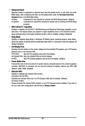
... the monitor display from the installed PCI graphics card, PCI Express graphics card, or the onboard VGA. Options are: 32M, 64M (default), 128M, 256M, Disabled. GA-M61PME-S2P Motherboard - 38 - After configuring this memory for entering the BIOS Setup program. (Default) System A password is installed. PCI Slot Sets the PCI graphics card as...
... the monitor display from the installed PCI graphics card, PCI Express graphics card, or the onboard VGA. Options are: 32M, 64M (default), 128M, 256M, Disabled. GA-M61PME-S2P Motherboard - 38 - After configuring this memory for entering the BIOS Setup program. (Default) System A password is installed. PCI Slot Sets the PCI graphics card as...
Manual
Page 40
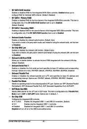
... to ECP or ECP+EPP mode. Onboard Parallel Port Enables or disables the onboard parallel port (LPT) and specifies its base I /O address and corresponding interrupt. GA-M61PME-S2P Motherboard - 40 - This item is configurable only if the NV SATA RAID function item is set to activate the boot ROM integrated with the onboard...
... to ECP or ECP+EPP mode. Onboard Parallel Port Enables or disables the onboard parallel port (LPT) and specifies its base I /O address and corresponding interrupt. GA-M61PME-S2P Motherboard - 40 - This item is configurable only if the NV SATA RAID function item is set to activate the boot ROM integrated with the onboard...

