Manual
Page 1
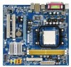
GA-M61PME-S2 AM2 socket motherboard for AMD AthlonTM 64 FX processor/ AMD AthlonTM 64 X2 Dual-Core processor/ AMD AthlonTM 64 processor/AMD SempronTM processor User's Manual Rev. 2003 12ME-M61PMES2-2003R
GA-M61PME-S2 AM2 socket motherboard for AMD AthlonTM 64 FX processor/ AMD AthlonTM 64 X2 Dual-Core processor/ AMD AthlonTM 64 processor/AMD SempronTM processor User's Manual Rev. 2003 12ME-M61PMES2-2003R

Manual
Page 2
Motherboard GA-M61PME-S2 Jan. 16, 2008 Motherboard GA-M61PME-S2 Jan. 16, 2008
Motherboard GA-M61PME-S2 Jan. 16, 2008 Motherboard GA-M61PME-S2 Jan. 16, 2008
Manual
Page 4
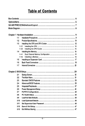
Table of Contents Box Contents ...6 OptionalItems...6 GA-M61PME-S2 Motherboard Layout 7 Block Diagram...8 Chapter 1 Hardware Installation 9 1-1 Installation Precautions 9 1-2 Product Specifications 10 1-3 Installing the CPU and CPU Cooler 12 1-3-1 Installing the CPU 12 1-3-2 Installing the ...
Table of Contents Box Contents ...6 OptionalItems...6 GA-M61PME-S2 Motherboard Layout 7 Block Diagram...8 Chapter 1 Hardware Installation 9 1-1 Installation Precautions 9 1-2 Product Specifications 10 1-3 Installing the CPU and CPU Cooler 12 1-3-1 Installing the CPU 12 1-3-2 Installing the ...
Manual
Page 6
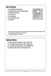
Box Contents GA-M61PME-S2 motherboard Motherboard driver disk (For Windows Vista) Motherboard driver disk User's Manual One IDE cable One SATA 3Gb/s cable I/O Shield • The box contents above ...
Box Contents GA-M61PME-S2 motherboard Motherboard driver disk (For Windows Vista) Motherboard driver disk User's Manual One IDE cable One SATA 3Gb/s cable I/O Shield • The box contents above ...
Manual
Page 10
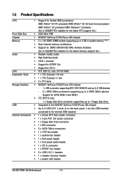
... supporting up to 8 GB of system memory (Note 1) Dual channel memory architecture Support for DDR2 800/667/533 MHz memory modules (Go to GIGABYTE's website for the latest memory support list.) Audio Realtek AL662 codec High Definition Audio 2/4/5.1-channel Support for S/PDIF Out ...header 1 x front panel audio header 1 x CD In connector 1 x S/PDIF Out header 2 x USB 2.0/1.1 headers 1 x chassis intrusion header 1 x power LED header GA-M61PME-S2 Motherboard - 10 -
... supporting up to 8 GB of system memory (Note 1) Dual channel memory architecture Support for DDR2 800/667/533 MHz memory modules (Go to GIGABYTE's website for the latest memory support list.) Audio Realtek AL662 codec High Definition Audio 2/4/5.1-channel Support for S/PDIF Out ...header 1 x front panel audio header 1 x CD In connector 1 x S/PDIF Out header 2 x USB 2.0/1.1 headers 1 x chassis intrusion header 1 x power LED header GA-M61PME-S2 Motherboard - 10 -

Manual
Page 12
..., otherwise overheating and damage of the Socket AM2 CPU Socket A Small Triangle Marking Denotes CPU Pin One AM2 CPU GA-M61PME-S2 Motherboard - 12 - mended that the motherboard supports the CPU. (Go to GIGABYTE's website for the peripherals. The CPU cannot be set the frequency beyond hardware specifications since it does not meet the...
..., otherwise overheating and damage of the Socket AM2 CPU Socket A Small Triangle Marking Denotes CPU Pin One AM2 CPU GA-M61PME-S2 Motherboard - 12 - mended that the motherboard supports the CPU. (Go to GIGABYTE's website for the peripherals. The CPU cannot be set the frequency beyond hardware specifications since it does not meet the...

Manual
Page 14
... retention frame. Use extreme care when removing the CPU cooler because the thermal grease/tape between the CPU cooler and CPU may damage the CPU. GA-M61PME-S2 Motherboard - 14 - Step 4: Turn the cam handle from the left side to the right side (as the example.) Step 1: Apply an ... CPU. 1-3-2 Installing the CPU Cooler Follow the steps below to correctly install the CPU cooler on the CPU. (The following procedure uses the GIGABYTE cooler as the picture above shows) to lock into place. (Refer to your CPU cooler installation manual for instructions on installing the cooler.) Step...
... retention frame. Use extreme care when removing the CPU cooler because the thermal grease/tape between the CPU cooler and CPU may damage the CPU. GA-M61PME-S2 Motherboard - 14 - Step 4: Turn the cam handle from the left side to the right side (as the example.) Step 1: Apply an ... CPU. 1-3-2 Installing the CPU Cooler Follow the steps below to correctly install the CPU cooler on the CPU. (The following procedure uses the GIGABYTE cooler as the picture above shows) to lock into place. (Refer to your CPU cooler installation manual for instructions on installing the cooler.) Step...

Manual
Page 16
... retaining clips at both ends of the memory socket. Place the memory module on the memory and insert it can only fit in one direction. GA-M61PME-S2 Motherboard - 16 - Follow the steps below to the memory module. 1-4-2 Installing a Memory Before installing a memory module , make sure to turn off the computer and unplug...
... retaining clips at both ends of the memory socket. Place the memory module on the memory and insert it can only fit in one direction. GA-M61PME-S2 Motherboard - 16 - Follow the steps below to the memory module. 1-4-2 Installing a Memory Before installing a memory module , make sure to turn off the computer and unplug...
Manual
Page 18
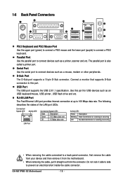
... side to 100 Mbps data rate. D-Sub Port The D-Sub port supports a 15-pin D-Sub connector. USB Port The USB port supports the USB 2.0/1.1 specification. GA-M61PME-S2 Motherboard - 18 -
... side to 100 Mbps data rate. D-Sub Port The D-Sub port supports a 15-pin D-Sub connector. USB Port The USB port supports the USB 2.0/1.1 specification. GA-M61PME-S2 Motherboard - 18 -
Manual
Page 20
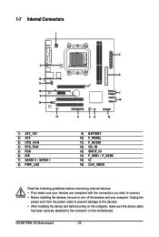
... sure your devices are compliant with the connectors you wish to connect. • Before installing the devices, be sure to the connector on the motherboard. GA-M61PME-S2 Motherboard - 20 - Unplug the power cord from the power outlet to prevent damage to the devices. • After installing the device and before connecting external...
... sure your devices are compliant with the connectors you wish to connect. • Before installing the devices, be sure to the connector on the motherboard. GA-M61PME-S2 Motherboard - 20 - Unplug the power cord from the power outlet to prevent damage to the devices. • After installing the device and before connecting external...
Manual
Page 22
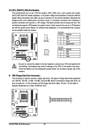
... • Be sure to connect fan cables to the fan headers to connect it is the ground wire. The types of different color. 33 1 34 2 GA-M61PME-S2 Motherboard - 22 - When connecting a fan cable, be installed inside the chassis. 3/4) CPU_FAN/SYS_FAN (Fan Headers) The motherboard has a 4-pin CPU fan header (CPU_FAN) and a 3-pin...
... • Be sure to connect fan cables to the fan headers to connect it is the ground wire. The types of different color. 33 1 34 2 GA-M61PME-S2 Motherboard - 22 - When connecting a fan cable, be installed inside the chassis. 3/4) CPU_FAN/SYS_FAN (Fan Headers) The motherboard has a 4-pin CPU fan header (CPU_FAN) and a 3-pin...
Manual
Page 24
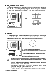
... the orientation of the positive side (+) and the negative side (-) of purchase or local dealer if you are not able to indicate system power status. GA-M61PME-S2 Motherboard - 24 - The LED is on the chassis to replace the battery by removing the battery: 1. The LED keeps blinking when the system is in...
... the orientation of the positive side (+) and the negative side (-) of purchase or local dealer if you are not able to indicate system power status. GA-M61PME-S2 Motherboard - 24 - The LED is on the chassis to replace the battery by removing the battery: 1. The LED keeps blinking when the system is in...

Manual
Page 26
... the wire assignments of the module connector match the pin assignments of the front and back panel audio connections simultaneously. Definition 1 CD-L 2 GND 1 3 GND 4 CD-R GA-M61PME-S2 Motherboard - 26 - For information about connecting the front panel audio module that has different wire assignments, please contact the chassis manufacturer. 12) CD_IN (CD In...
... the wire assignments of the module connector match the pin assignments of the front and back panel audio connections simultaneously. Definition 1 CD-L 2 GND 1 3 GND 4 CD-R GA-M61PME-S2 Motherboard - 26 - For information about connecting the front panel audio module that has different wire assignments, please contact the chassis manufacturer. 12) CD_IN (CD In...
Manual
Page 28
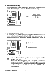
... touch the two pins for BIOS configurations). Definition 1 1 Signal 2 GND 16) CLR_CMOS (Clearing CMOS Jumper) Use this jumper to Chapter 2, "BIOS Setup," for a few seconds. GA-M61PME-S2 Motherboard - 28 - This function requires a chassis with chassis intrusion detection design. Failure to do so may cause damage to the motherboard. • After system restart...
... touch the two pins for BIOS configurations). Definition 1 1 Signal 2 GND 16) CLR_CMOS (Clearing CMOS Jumper) Use this jumper to Chapter 2, "BIOS Setup," for a few seconds. GA-M61PME-S2 Motherboard - 28 - This function requires a chassis with chassis intrusion detection design. Failure to do so may cause damage to the motherboard. • After system restart...
Manual
Page 30
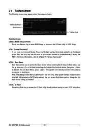
...access Boot Menu again to change the first boot device setting as needed. : Q-Flash Press the key to XpressRecovery2 during the POST. GA-M61PME-S2 Motherboard - 30 - To exit Boot Menu, press . After system restart, the device boot order will directly boot from the device ...configured in Boot Menu is effective for subsequent access to access the Q-Flash utility directly without entering BIOS Setup. M61PME-S2 D1a . . . . : BIOS Setup/Q-Flash : XpressRecovery2 : Boot Menu : Qflash 12/17/2007-NV-MCP61-6A61KG09C-00 Function Keys Function ...
...access Boot Menu again to change the first boot device setting as needed. : Q-Flash Press the key to XpressRecovery2 during the POST. GA-M61PME-S2 Motherboard - 30 - To exit Boot Menu, press . After system restart, the device boot order will directly boot from the device ...configured in Boot Menu is effective for subsequent access to access the Q-Flash utility directly without entering BIOS Setup. M61PME-S2 D1a . . . . : BIOS Setup/Q-Flash : XpressRecovery2 : Boot Menu : Qflash 12/17/2007-NV-MCP61-6A61KG09C-00 Function Keys Function ...
Manual
Page 32
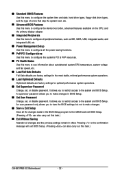
... and exit BIOS Setup. (Pressing can also carry out this menu to configure the system's PCI & PnP resources. PC Health Status Use this task.) GA-M61PME-S2 Motherboard - 32 - An user password only allows you to make changes. Save & Exit Setup Save all the changes made in BIOS Setup. Set...
... and exit BIOS Setup. (Pressing can also carry out this menu to configure the system's PCI & PnP resources. PC Health Status Use this task.) GA-M61PME-S2 Motherboard - 32 - An user password only allows you to make changes. Save & Exit Setup Save all the changes made in BIOS Setup. Set...
Manual
Page 34
... error. The following fields display your system. Cylinder Number of floppy disk drive installed in your hard drive specifications. Base Memory Also called conventional memory. GA-M61PME-S2 Motherboard - 34 - Drive A Allows you to selects the type of cylinders.
... error. The following fields display your system. Cylinder Number of floppy disk drive installed in your hard drive specifications. Base Memory Also called conventional memory. GA-M61PME-S2 Motherboard - 34 - Drive A Allows you to selects the type of cylinders.
Manual
Page 36
...) Frame Buffer Size Frame buffer size is installed. Onboard GPU Enables or disables the onboard VGA function. Away Mode allows the system to Always Enable. GA-M61PME-S2 Motherboard - 36 - Options are: 32M, 64M (default), 128M, 256M, Disabled. This feature allows your hard drive. Enable If No Ext PEG Activates the onboard VGA...
...) Frame Buffer Size Frame buffer size is installed. Onboard GPU Enables or disables the onboard VGA function. Away Mode allows the system to Always Enable. GA-M61PME-S2 Motherboard - 36 - Options are: 32M, 64M (default), 128M, 256M, Disabled. This feature allows your hard drive. Enable If No Ext PEG Activates the onboard VGA...
Manual
Page 38
... onboard parallel (LPT) port. Onboard LAN Boot ROM Allows you to Disabled. Parallel Port Mode Selects an operating mode for the integrated SATA 3Gb/s controller. GA-M61PME-S2 Motherboard - 38 - This item is configurable only if the NV SATA RAID function item is set this item to configure RAID for individual SATA channel...
... onboard parallel (LPT) port. Onboard LAN Boot ROM Allows you to Disabled. Parallel Port Mode Selects an operating mode for the integrated SATA 3Gb/s controller. GA-M61PME-S2 Motherboard - 38 - This item is configurable only if the NV SATA RAID function item is set this item to configure RAID for individual SATA channel...
Manual
Page 40
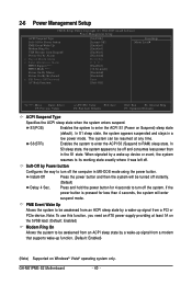
... for less than in MS-DOS mode using the power button. In S1 sleep state, the system appears suspended and stays in a low power mode. GA-M61PME-S2 Motherboard - 40 -
... for less than in MS-DOS mode using the power button. In S1 sleep state, the system appears suspended and stays in a low power mode. GA-M61PME-S2 Motherboard - 40 -


