
Manual
Page 1
GA-M59SLI-S5 / GA-M59SLI-S4 AMD Socket AM2 Processor Motherboard User's Manual Rev. 1003 12ME-M59SLIS5-1003R * The WEEE marking on the product indicates this product must not be disposed of with user's other household waste and must be handed over to a designated collection point for the recycling of waste electrical and electronic equipment!! * The WEEE marking applies only in European Union's member states.
GA-M59SLI-S5 / GA-M59SLI-S4 AMD Socket AM2 Processor Motherboard User's Manual Rev. 1003 12ME-M59SLIS5-1003R * The WEEE marking on the product indicates this product must not be disposed of with user's other household waste and must be handed over to a designated collection point for the recycling of waste electrical and electronic equipment!! * The WEEE marking applies only in European Union's member states.

Manual
Page 4
Table of Contents ItemChecklist ...6 OptionalAccessories ...6 GA-M59SLI-S5 Motherboard Layout 7 GA-M59SLI-S4 Motherboard Layout 8 Block Diagram ...9 Chapter 1 Hardware Installation 11 1-1 Considerations Prior to Installation 11 1-2 Feature Summary 12 1-3 Installation of the CPU and CPU Cooler 15 1-3-1 Installation ...
Table of Contents ItemChecklist ...6 OptionalAccessories ...6 GA-M59SLI-S5 Motherboard Layout 7 GA-M59SLI-S4 Motherboard Layout 8 Block Diagram ...9 Chapter 1 Hardware Installation 11 1-1 Considerations Prior to Installation 11 1-2 Feature Summary 12 1-3 Installation of the CPU and CPU Cooler 15 1-3-1 Installation ...
Manual
Page 5
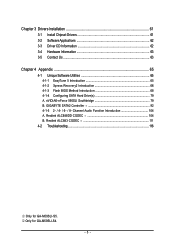
... ...63 Chapter 4 Appendix 65 4-1 Unique Software Utilities 65 4-1-1 EasyTune 5 Introduction 65 4-1-2 Xpress Recovery2 Introduction 66 4-1-3 Flash BIOS Method Introduction 68 4-1-4 Configuring SATA Hard Drive(s 79 A. GIGABYTE SATA2 Controller 92 4-1-5 2- / 4- / 6- / 8- Only for GA-M59SLI-S5. Channel Audio Function Introduction 104 A. nVIDIA® nForce 590SLI Southbridge 79 B. Realtek ALC883 CODEC 111 4-2 Troubleshooting 116 Only for GA-M59SLI-S4. - 5 -
... ...63 Chapter 4 Appendix 65 4-1 Unique Software Utilities 65 4-1-1 EasyTune 5 Introduction 65 4-1-2 Xpress Recovery2 Introduction 66 4-1-3 Flash BIOS Method Introduction 68 4-1-4 Configuring SATA Hard Drive(s 79 A. GIGABYTE SATA2 Controller 92 4-1-5 2- / 4- / 6- / 8- Only for GA-M59SLI-S5. Channel Audio Function Introduction 104 A. nVIDIA® nForce 590SLI Southbridge 79 B. Realtek ALC883 CODEC 111 4-2 Troubleshooting 116 Only for GA-M59SLI-S4. - 5 -
Manual
Page 6
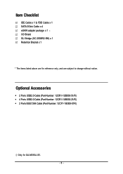
Optional Accessories Š 2 Ports USB2.0 Cable (Part Number: 12CR1-1UB030-51/R) Š 4 Ports USB2.0 Cable (Part Number: 12CR1-1UB030-21/R) Š 2 Ports IEEE1394 Cable (Part Number: 12CF1-1IE008-01R) Only for reference only, and are subject to change without notice. Item Checklist IDE Cable x 1 & FDD Cable x 1 SATA 3Gb/s Cable x 4 eSATA adapter package x 1 I/O Shield SLI Bridge (GC-DGBR2-RH) x 1 Retention Bracket x 1 * The items listed above are for GA-M59SLI-S5. - 6 -
Optional Accessories Š 2 Ports USB2.0 Cable (Part Number: 12CR1-1UB030-51/R) Š 4 Ports USB2.0 Cable (Part Number: 12CR1-1UB030-21/R) Š 2 Ports IEEE1394 Cable (Part Number: 12CF1-1IE008-01R) Only for reference only, and are subject to change without notice. Item Checklist IDE Cable x 1 & FDD Cable x 1 SATA 3Gb/s Cable x 4 eSATA adapter package x 1 I/O Shield SLI Bridge (GC-DGBR2-RH) x 1 Retention Bracket x 1 * The items listed above are for GA-M59SLI-S5. - 6 -

Manual
Page 7
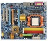
... Marvell 88E1116 AUDIO PCIE_1 Marvell 88E1116 nVIDIA® nForce 590SLI Northbridge GA-M59SLI-S5 PCIE_16_1 IDE1 FDD SATAII5 SATAII4 SYS_FAN CODEC PCIE_2 PCIE_8 CD_IN SPDIF_I PCIE_16_2 IT8716 PCI1 PCI2 CI TPM F1_1394 nVIDIA® nForce 590SLI Southbridge SATAII1 SATAII3 TSB43AB23 SATAII0 SATAII2 GIGABYTE SATA2 BAT Backup BIOS CLR_CMOS Main BIOS F2_1394 JSATAII1 F_PANEL F_USB3...
... Marvell 88E1116 AUDIO PCIE_1 Marvell 88E1116 nVIDIA® nForce 590SLI Northbridge GA-M59SLI-S5 PCIE_16_1 IDE1 FDD SATAII5 SATAII4 SYS_FAN CODEC PCIE_2 PCIE_8 CD_IN SPDIF_I PCIE_16_2 IT8716 PCI1 PCI2 CI TPM F1_1394 nVIDIA® nForce 590SLI Southbridge SATAII1 SATAII3 TSB43AB23 SATAII0 SATAII2 GIGABYTE SATA2 BAT Backup BIOS CLR_CMOS Main BIOS F2_1394 JSATAII1 F_PANEL F_USB3...
Manual
Page 9
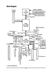
... x1 PCI-ECLK (100MHz) Hyper Transport Bus PCI Express x1 LAN1 LAN2 RJ45 RJ45 Marvell 88E1116 x 2 PCI Bus TSB43AB23 nVIDIA® nForce 590SLI Southbridge CODEC GIGABYTE SATA2 LPC BUS Dual BIOS 6 SATA 3Gb/s ATA33/66/100/133 IDE Channel Floppy IT8716 LPT Port COM Port PS/2 KB/Mouse 2 PCI 10 USB... PCI Express x16 3 IEEE1394a Surround Speaker Out Center/Subwoofer Speaker Out Side Speaker Out MIC Line-Out Line-In SPDIF In SPDIF Out Only for GA-M59SLI-S5. - 9 -
... x1 PCI-ECLK (100MHz) Hyper Transport Bus PCI Express x1 LAN1 LAN2 RJ45 RJ45 Marvell 88E1116 x 2 PCI Bus TSB43AB23 nVIDIA® nForce 590SLI Southbridge CODEC GIGABYTE SATA2 LPC BUS Dual BIOS 6 SATA 3Gb/s ATA33/66/100/133 IDE Channel Floppy IT8716 LPT Port COM Port PS/2 KB/Mouse 2 PCI 10 USB... PCI Express x16 3 IEEE1394a Surround Speaker Out Center/Subwoofer Speaker Out Side Speaker Out MIC Line-Out Line-In SPDIF In SPDIF Out Only for GA-M59SLI-S5. - 9 -
Manual
Page 12
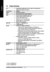
...Only for Serial ATA Š GIGABYTE SATA2 Controller - 2 SATA 3Gb/s connectors (JSATAII0, JSATAII1), allowing connection of 6 SATA 3Gb/s devices - Supports data striping (RAID 0), mirroring (RAID 1), striping+mirroring (RAID 0+1), RAID 5 and JBOD for GA-M59SLI-S5. GA-M59SLI-S5/GA-M59SLI-S4 Motherboard - 12 - Only for... Feature Summary CPU Front Side Bus Chipset LAN Audio IEEE 1394 Storage O.S Support Memory Expanstion Slots Š Socket AM2 for GA-M59SLI-S4. TSB43AB23 chip Š 3 IEEE1394a ports Š nVIDIA® nForce 590SLI Southbridge - 1 FDD connector, allowing connection of ...
...Only for Serial ATA Š GIGABYTE SATA2 Controller - 2 SATA 3Gb/s connectors (JSATAII0, JSATAII1), allowing connection of 6 SATA 3Gb/s devices - Supports data striping (RAID 0), mirroring (RAID 1), striping+mirroring (RAID 0+1), RAID 5 and JBOD for GA-M59SLI-S5. GA-M59SLI-S5/GA-M59SLI-S4 Motherboard - 12 - Only for... Feature Summary CPU Front Side Bus Chipset LAN Audio IEEE 1394 Storage O.S Support Memory Expanstion Slots Š Socket AM2 for GA-M59SLI-S4. TSB43AB23 chip Š 3 IEEE1394a ports Š nVIDIA® nForce 590SLI Southbridge - 1 FDD connector, allowing connection of ...
Manual
Page 13
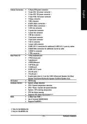
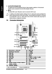
Only for GA-M59SLI-S5. Hardware Installation English Internal Connectors Š 1 24-pin ATX power connector Š 1 8-pin ATX 12V power connector Š 1 4-pin ATX 12V power connector Š 1 4-pin ... failure warning Š Supports CPU Smart Fan function(Note 2) BIOS Š 2 4Mbit flash ROM Š Use of licensed AWARD BIOS Š Supports DualBIOS Only for GA-M59SLI-S4. - 13 -
Only for GA-M59SLI-S5. Hardware Installation English Internal Connectors Š 1 24-pin ATX power connector Š 1 8-pin ATX 12V power connector Š 1 4-pin ATX 12V power connector Š 1 4-pin ... failure warning Š Supports CPU Smart Fan function(Note 2) BIOS Š 2 4Mbit flash ROM Š Use of licensed AWARD BIOS Š Supports DualBIOS Only for GA-M59SLI-S4. - 13 -
Manual
Page 14
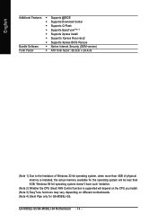
Windows 64-bit operating system doesn't have such limitation. (Note 2) Whether the CPU Smart FAN Control function is installed, the actual memory available for GA-M59SLI-S5. GA-M59SLI-S5/GA-M59SLI-S4 Motherboard - 14 - English Additional Features Š Supports @BIOS Š Supports Download Center Š Supports Q-Flash Š Supports EasyTune(Note 3) Š Supports Xpress Install Š Supports ...
Windows 64-bit operating system doesn't have such limitation. (Note 2) Whether the CPU Smart FAN Control function is installed, the actual memory available for GA-M59SLI-S5. GA-M59SLI-S5/GA-M59SLI-S4 Motherboard - 14 - English Additional Features Š Supports @BIOS Š Supports Download Center Š Supports Q-Flash Š Supports EasyTune(Note 3) Š Supports Xpress Install Š Supports ...

Manual
Page 16
Install all the CPU cooler components (Please refer to the CPU_FAN connector located on the surface of the CPU. GA-M59SLI-S5/GA-M59SLI-S4 Motherboard - 16 - Fig.2 Please connect the CPU cooler power connector to the cooler manual for heat dissipation or using extreme care when removing the CPU ...
Install all the CPU cooler components (Please refer to the CPU_FAN connector located on the surface of the CPU. GA-M59SLI-S5/GA-M59SLI-S4 Motherboard - 16 - Fig.2 Please connect the CPU cooler power connector to the cooler manual for heat dissipation or using extreme care when removing the CPU ...

Manual
Page 18
... DDRII2 DS/SS - To enable Dual Channel mode with four memory modules, it is recommended to operate the Dual Channel Technology, follow the guidelines below: 1. GA-M59SLI-S5/GA-M59SLI-S4 Motherboard - 18 - To enable Dual Channel mode with two memory modules (it is recommended to achieve Dual Channel mode, we recommend installing them into DIMM... Channel mode will double. Due to CPU limitation, if you wish to use memory modules of the same color. 3. English Dual Channel Memory Configuration The GA-M59SLI-S5/GA-M59SLI-S4 supports the Dual Channel Technology.
... DDRII2 DS/SS - To enable Dual Channel mode with four memory modules, it is recommended to operate the Dual Channel Technology, follow the guidelines below: 1. GA-M59SLI-S5/GA-M59SLI-S4 Motherboard - 18 - To enable Dual Channel mode with two memory modules (it is recommended to achieve Dual Channel mode, we recommend installing them into DIMM... Channel mode will double. Due to CPU limitation, if you wish to use memory modules of the same color. 3. English Dual Channel Memory Configuration The GA-M59SLI-S5/GA-M59SLI-S4 supports the Dual Channel Technology.

Manual
Page 20
... overall system configurations. Before you begin-The exact power requirements will depend on the GAM59SLI-S5/GA-M59SLI-S4 motherboard. English 1-6 Setup of identical brand and chips. GA-M59SLI-S5/GA-M59SLI-S4 Motherboard - 20 - This section introduces steps to ensure better display performance. For example: GIGABYTE GV-NX76T256D-RH). Please refer to the table below to check recommended power for...
... overall system configurations. Before you begin-The exact power requirements will depend on the GAM59SLI-S5/GA-M59SLI-S4 motherboard. English 1-6 Setup of identical brand and chips. GA-M59SLI-S5/GA-M59SLI-S4 Motherboard - 20 - This section introduces steps to ensure better display performance. For example: GIGABYTE GV-NX76T256D-RH). Please refer to the table below to check recommended power for...
Manual
Page 22
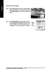
The NVIDIA control panel will restart after you click Apply. GA-M59SLI-S5/GA-M59SLI-S4 Motherboard - 22 - System will appear. English Graphics Card Driver Setting: Step 1: After installing graphics card driver in operating system, right-click the NVIDIA icon in the SLI multi-GPU dialog box. Then the SLI configuration is completed. Step 2: Select SLI multi-GPU from the side menu and then select the Enable SLI multi-GPU checkbox in your system tray and then select NVIDIA Display.
The NVIDIA control panel will restart after you click Apply. GA-M59SLI-S5/GA-M59SLI-S4 Motherboard - 22 - System will appear. English Graphics Card Driver Setting: Step 1: After installing graphics card driver in operating system, right-click the NVIDIA icon in the SLI multi-GPU dialog box. Then the SLI configuration is completed. Step 2: Select SLI multi-GPU from the side menu and then select the Enable SLI multi-GPU checkbox in your system tray and then select NVIDIA Display.
Manual
Page 23
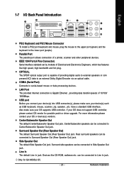
... or com pressed AC3 data to the lower port (purple). Also make sure your OS does not support USB controller, please contact OS vendor for GA-M59SLI-S5. - 23 - can be connected to Surround Speaker Out (Rear Speaker Out) jack. Hardware Installation English 1-7 I/O Back Panel Introduction PS/2 Keyboard and PS/2 Mouse Connector To...
... or com pressed AC3 data to the lower port (purple). Also make sure your OS does not support USB controller, please contact OS vendor for GA-M59SLI-S5. - 23 - can be connected to Surround Speaker Out (Rear Speaker Out) jack. Hardware Installation English 1-7 I/O Back Panel Introduction PS/2 Keyboard and PS/2 Mouse Connector To...
Manual
Page 24
MIC In The default MIC In jack. Only microphones still MUST be connected to MIC In jack. Only for GA-M59SLI-S5. Microphone must be connected to perform different functions via the audio software. channel audio setup steps for detailed software ... C I SATAII4 / SATAII5 22) BAT 11) JSATAII0 / JSATAII1 Only for GA-M59SLI-S4. Stereo speakers, earphone or front surround speakers can be connected to the 2-/4-/6-/8- Please refer to Line Out (Front Speaker Out) jack. GA-M59SLI-S5/GA-M59SLI-S4 Motherboard - 24 - In addition to the default speakers settings, the ~ audio...
MIC In The default MIC In jack. Only microphones still MUST be connected to MIC In jack. Only for GA-M59SLI-S5. Microphone must be connected to perform different functions via the audio software. channel audio setup steps for detailed software ... C I SATAII4 / SATAII5 22) BAT 11) JSATAII0 / JSATAII1 Only for GA-M59SLI-S4. Stereo speakers, earphone or front surround speakers can be connected to the 2-/4-/6-/8- Please refer to Line Out (Front Speaker Out) jack. GA-M59SLI-S5/GA-M59SLI-S4 Motherboard - 24 - In addition to the default speakers settings, the ~ audio...
Manual
Page 25
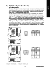
... all the components on the motherboard. Only for GA-M59SLI-S5. It is used (400W or greater). otherwise, please do not remove it. 3 4 1 2 ATX_12V Pin No. 1 2 3 4 Definition GND GND +12V +12V 5 8 1 4 ATX_12V_2X Pin No. 1 2 3 4 5 6 7 8 Definition GND GND GND GND +12V +12V +12V +12V Only for GA-M59SLI-S4. - 25 - If the ATX_12V power connector is able...
... all the components on the motherboard. Only for GA-M59SLI-S5. It is used (400W or greater). otherwise, please do not remove it. 3 4 1 2 ATX_12V Pin No. 1 2 3 4 Definition GND GND +12V +12V 5 8 1 4 ATX_12V_2X Pin No. 1 2 3 4 5 6 7 8 Definition GND GND GND GND +12V +12V +12V +12V Only for GA-M59SLI-S4. - 25 - If the ATX_12V power connector is able...
Manual
Page 26
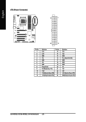
English ATX (Power Connector) 13 1 24 12 Pin No. 1 2 3 4 5 6 7 8 9 10 11 12 Definition 3.3V 3.3V GND +5V GND +5V GND Power Good 5V SB(stand by +5V) +12V +12V(Only for 24-pin ATX) 3.3V(Only for 24-pin ATX) Pin No. 13 14 15 16 17 18 19 20 21 22 23 24 Definition 3.3V -12V GND PS_ON(soft On/Off) GND GND GND -5V +5V +5V +5V (Only for 24-pin ATX) GND(Only for 24-pin ATX) GA-M59SLI-S5/GA-M59SLI-S4 Motherboard - 26 -
English ATX (Power Connector) 13 1 24 12 Pin No. 1 2 3 4 5 6 7 8 9 10 11 12 Definition 3.3V 3.3V GND +5V GND +5V GND Power Good 5V SB(stand by +5V) +12V +12V(Only for 24-pin ATX) 3.3V(Only for 24-pin ATX) Pin No. 13 14 15 16 17 18 19 20 21 22 23 24 Definition 3.3V -12V GND PS_ON(soft On/Off) GND GND GND -5V +5V +5V +5V (Only for 24-pin ATX) GND(Only for 24-pin ATX) GA-M59SLI-S5/GA-M59SLI-S4 Motherboard - 26 -
Manual
Page 28
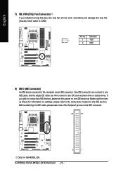
... instructions located on one IDE cable, and the single IDE cable can connect to one IDE device as Master and the other as Slave (for GA-M59SLI-S4. English 7) SB_FAN (Chip Fan Connector) If you wish to connect two IDE devices, please set the jumper on the IDE device...
... instructions located on one IDE cable, and the single IDE cable can connect to one IDE device as Master and the other as Slave (for GA-M59SLI-S4. English 7) SB_FAN (Chip Fan Connector) If you wish to connect two IDE devices, please set the jumper on the IDE device...
Manual
Page 29
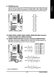
... by GIGABYTE SATA2) SATA 3Gb/s can provide up to the FDD drive. Before attaching the FDD cable, please take note of the cable connects to 300MB/s transfer rate. Hardware Installation The types of FDD drives supported are: 360KB, 720KB, 1.2MB, 1.44MB and 2.88MB. Please refer to the BIOS setting for GA-M59SLI-S5. 7 JSATAII0...
... by GIGABYTE SATA2) SATA 3Gb/s can provide up to the FDD drive. Before attaching the FDD cable, please take note of the cable connects to 300MB/s transfer rate. Hardware Installation The types of FDD drives supported are: 360KB, 720KB, 1.2MB, 1.44MB and 2.88MB. Please refer to the BIOS setting for GA-M59SLI-S5. 7 JSATAII0...
Manual
Page 30
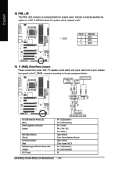
Pin 3: NC Pin 4: Data(-) Open: Normal Close: Reset Hardware System Open: Normal Close: Power On/Off Pin 1: LED anode(+) Pin 2: LED cathode(-) NC GA-M59SLI-S5/GA-M59SLI-S4 Motherboard - 30 - Message LED/ Power/ Sleep LED Speaker Connector Power Switch MSG+ MSG- RESRES+ NC HD (IDE Hard Disk Active LED) (Blue) SPEAK (Speaker Connector) (...
Pin 3: NC Pin 4: Data(-) Open: Normal Close: Reset Hardware System Open: Normal Close: Power On/Off Pin 1: LED anode(+) Pin 2: LED cathode(-) NC GA-M59SLI-S5/GA-M59SLI-S4 Motherboard - 30 - Message LED/ Power/ Sleep LED Speaker Connector Power Switch MSG+ MSG- RESRES+ NC HD (IDE Hard Disk Active LED) (Blue) SPEAK (Speaker Connector) (...