Manual
Page 4
Table of Contents ItemChecklist ...6 OptionalAccessories ...6 GA-M57SLI-S4 Motherboard Layout 7 Block Diagram ...8 Chapter 1 Hardware Installation 9 1-1 Considerations Prior to Installation 9 1-2 Feature Summary 10 1-3 Installation of the CPU and CPU Cooler 12 1-3-1 Installation of the CPU 12 1-3-2 Installation of the CPU Cooler 13 1-4 Installation of Memory 14 1-5 Installation of Expansion Cards 16 1-6 Setup of an SLI (Scalable...
Table of Contents ItemChecklist ...6 OptionalAccessories ...6 GA-M57SLI-S4 Motherboard Layout 7 Block Diagram ...8 Chapter 1 Hardware Installation 9 1-1 Considerations Prior to Installation 9 1-2 Feature Summary 10 1-3 Installation of the CPU and CPU Cooler 12 1-3-1 Installation of the CPU 12 1-3-2 Installation of the CPU Cooler 13 1-4 Installation of Memory 14 1-5 Installation of Expansion Cards 16 1-6 Setup of an SLI (Scalable...
Manual
Page 8
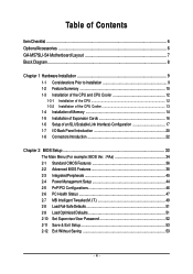
Block Diagram SLI PCIe CLK (100 MHz) AMD Socket AM2 CPU CPU CLK+/-(200 MHz) DDRII 800/667/533/400 MHz DIMM Hyper Transport Bus Dual Channel Memory PCI Express x8 PCI Express x16 Marvell 88E1116 LAN RJ45 PCI Express Bus x1 x1 x1 PCIe CLK (100 MHz) 3 PCI Express x1 PCI Bus TSB43AB23 3 IEEE 1394a nVIDIA® nForce 570-SLI BIOS 6 SATA 3Gb/s ATA-33/66/100/133 IDE Channel CODEC LPC BUS IT8716 Floppy LPT Port COM Port 10 USB Ports PS/2 KB/Mouse Surround Speaker Out Center/Subwoofer Speaker Out Side Speaker Out MIC Line-Out Line-In SPDIF In SPDIF Out 2 PCI PCI CLK (33 MHz) - 8 -
Block Diagram SLI PCIe CLK (100 MHz) AMD Socket AM2 CPU CPU CLK+/-(200 MHz) DDRII 800/667/533/400 MHz DIMM Hyper Transport Bus Dual Channel Memory PCI Express x8 PCI Express x16 Marvell 88E1116 LAN RJ45 PCI Express Bus x1 x1 x1 PCIe CLK (100 MHz) 3 PCI Express x1 PCI Bus TSB43AB23 3 IEEE 1394a nVIDIA® nForce 570-SLI BIOS 6 SATA 3Gb/s ATA-33/66/100/133 IDE Channel CODEC LPC BUS IT8716 Floppy LPT Port COM Port 10 USB Ports PS/2 KB/Mouse Surround Speaker Out Center/Subwoofer Speaker Out Side Speaker Out MIC Line-Out Line-In SPDIF In SPDIF Out 2 PCI PCI CLK (33 MHz) - 8 -
Manual
Page 10
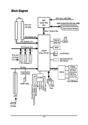
..., allowing connection of 6 SATA 3Gb/s devices - Supports RAID 0, RAID 1, RAID 0+1, and RAID 5 for Serial ATA O.S Support Š Microsoft Windows Vista/2000/XP Memory Š 4 DDRII DIMM memory slots (supports up to 16 GB memory)(Note 1) Š Supports dual channel DDRII 800/667/533/400 DIMMs Š Supports 1.8V DDRII DIMMs Š Supports ECC... Š 1 CD In connector Š 1 S/PDIF In connector Š 3 USB 2.0/1.1 connectors for additional 6 USB 2.0/1.1 ports by cables Š 1 chassis intrusion connector Š 1 power LED connector GA-M57SLI-S4 Motherboard - 10 -
..., allowing connection of 6 SATA 3Gb/s devices - Supports RAID 0, RAID 1, RAID 0+1, and RAID 5 for Serial ATA O.S Support Š Microsoft Windows Vista/2000/XP Memory Š 4 DDRII DIMM memory slots (supports up to 16 GB memory)(Note 1) Š Supports dual channel DDRII 800/667/533/400 DIMMs Š Supports 1.8V DDRII DIMMs Š Supports ECC... Š 1 CD In connector Š 1 S/PDIF In connector Š 3 USB 2.0/1.1 connectors for additional 6 USB 2.0/1.1 ports by cables Š 1 chassis intrusion connector Š 1 power LED connector GA-M57SLI-S4 Motherboard - 10 -
Manual
Page 11
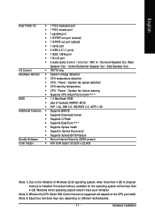
... factor; 30.5cm x 23.4cm (Note 1) Due to the limitation of Windows 32-bit operating system, when more than 4 GB of physical memory is supported will be less than 4 GB; Windows 64-bit operating system doesn't have such limitation. (Note 2) Whether the CPU Smart FAN Control... function is installed, the actual memory available for the operating system will depend on the CPU you install. (Note 3) EasyTune functions may vary depending on different motherboards. - 11 - ...
... factor; 30.5cm x 23.4cm (Note 1) Due to the limitation of Windows 32-bit operating system, when more than 4 GB of physical memory is supported will be less than 4 GB; Windows 64-bit operating system doesn't have such limitation. (Note 2) Whether the CPU Smart FAN Control... function is installed, the actual memory available for the operating system will depend on the CPU you install. (Note 3) EasyTune functions may vary depending on different motherboards. - 11 - ...
Manual
Page 12
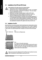
... so according to your hardware specifications including the CPU, graphics card, memory, hard drive, etc. 1-3-1 Installation of the CPU Check the CPU pins to set the frequency beyond hardware specifications since it into position making sure that none are bent. GA-M57SLI-S4 Motherboard - 12 - If you wish to see that the CPU pins...
... so according to your hardware specifications including the CPU, graphics card, memory, hard drive, etc. 1-3-1 Installation of the CPU Check the CPU pins to set the frequency beyond hardware specifications since it into position making sure that none are bent. GA-M57SLI-S4 Motherboard - 12 - If you wish to see that the CPU pins...

Manual
Page 14
... prevent hardware damage. 3. GA-M57SLI-S4 Motherboard - 14 - Before installing or removing memory modules, please make sure that memory of similar capacity, specifications and brand be installed in one direction. Notch DDRII Fig.1 The DIMM socket has a notch, so the DIMM memory module can be inserted only in one direction. Insert the DIMM memory module vertically into...
... prevent hardware damage. 3. GA-M57SLI-S4 Motherboard - 14 - Before installing or removing memory modules, please make sure that memory of similar capacity, specifications and brand be installed in one direction. Notch DDRII Fig.1 The DIMM socket has a notch, so the DIMM memory module can be inserted only in one direction. Insert the DIMM memory module vertically into...
Manual
Page 15
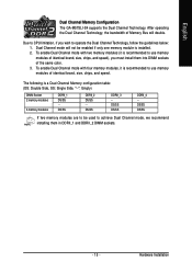
English Dual Channel Memory Configuration The GA-M57SLI-S4 supports the Dual Channel Technology. DS/SS DS/SS DDRII_4 - To enable Dual Channel mode with four memory modules, it is recommended to CPU limitation, if you must install them in DDRII_1 and DDRII_2 DIMM sockets. - 15 - The following...identical brand, size, chips, and speed), you wish to achieve Dual Channel mode, we recommend installing them into DIMM sockets of Memory Bus will not be used to operate the Dual Channel Technology, follow the guidelines below: 1. Hardware Installation After operating the Dual ...
English Dual Channel Memory Configuration The GA-M57SLI-S4 supports the Dual Channel Technology. DS/SS DS/SS DDRII_4 - To enable Dual Channel mode with four memory modules, it is recommended to CPU limitation, if you must install them in DDRII_1 and DDRII_2 DIMM sockets. - 15 - The following...identical brand, size, chips, and speed), you wish to achieve Dual Channel mode, we recommend installing them into DIMM sockets of Memory Bus will not be used to operate the Dual Channel Technology, follow the guidelines below: 1. Hardware Installation After operating the Dual ...
Manual
Page 36
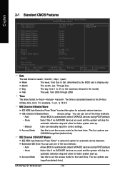
...[None] [None] [None] [None] [None] Drive A Drive B Floppy 3 Mode Support [1.44M, 3.5"] [None] [Disabled] Halt On [All, But Keyboard] Base Memory Extended Memory : Move Enter: Select F5: Previous Values 640K 511M +/-/PU/PD: Value F10: Save F6: Fail-Safe Defaults ESC: Exit F1: General Help F7: Optimized Defaults... SATA/IDE devices during POST(default) • None Select this if no SATA/IDE devices are : Large/Auto(default:Auto) GA-M57SLI-S4 Motherboard - 36 - Access Mode Use this to select this option for the hard drive. Extended IDE Drive You can manually input...
...[None] [None] [None] [None] [None] Drive A Drive B Floppy 3 Mode Support [1.44M, 3.5"] [None] [Disabled] Halt On [All, But Keyboard] Base Memory Extended Memory : Move Enter: Select F5: Previous Values 640K 511M +/-/PU/PD: Value F10: Save F6: Fail-Safe Defaults ESC: Exit F1: General Help F7: Optimized Defaults... SATA/IDE devices during POST(default) • None Select this if no SATA/IDE devices are : Large/Auto(default:Auto) GA-M57SLI-S4 Motherboard - 36 - Access Mode Use this to select this option for the hard drive. Extended IDE Drive You can manually input...

Manual
Page 37
...3.5" 3.5 inch double-sided drive; 1.44 MB capacity. (Default value) 3.5 inch double-sided drive; 2.88 MB capacity. it will be prompted. Memory The category is display-only which is determined by POST (Power On Self Test) of floppy disk drive A or drive B that may be detected and...Drive. (Default value) Drive A Drive A is detected during the POST. This is present during power up. English Capacity Capacity of memory located above 1 MB in the CPU's memory address map. - 37 - None No floppy drive installed. 360K, 5.25" 5.25 inch PC-type standard drive; 360 KB ...
...3.5" 3.5 inch double-sided drive; 1.44 MB capacity. (Default value) 3.5 inch double-sided drive; 2.88 MB capacity. it will be prompted. Memory The category is display-only which is determined by POST (Power On Self Test) of floppy disk drive A or drive B that may be detected and...Drive. (Default value) Drive A Drive A is detected during the POST. This is present during power up. English Capacity Capacity of memory located above 1 MB in the CPU's memory address map. - 37 - None No floppy drive installed. 360K, 5.25" 5.25 inch PC-type standard drive; 360 KB ...
Manual
Page 49
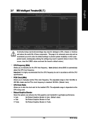
... CPU frequency be set the PCIe clock frequency. Robust Graphics Booster Select the options can enhance the VGA graphics card bandwidth to CPU, chipset, or memory and reduce the useful life of these components. This page is dependent on the CPU being used. English 2-7 MB Intelligent Tweaker(M.I.T.) CMOS Setup Utility-Copyright...
... CPU frequency be set the PCIe clock frequency. Robust Graphics Booster Select the options can enhance the VGA graphics card bandwidth to CPU, chipset, or memory and reduce the useful life of these components. This page is dependent on the CPU being used. English 2-7 MB Intelligent Tweaker(M.I.T.) CMOS Setup Utility-Copyright...

Manual
Page 50
... Voltage Sets the voltage settings for the memory. Normal sets the CPU voltage as CPU HT-Link required. (Default value) +0.025V ~ +0.375V Increase CPU HT-Link voltage by 0.025V to set the CPU voltage. Normal CPU Vcore Displays the normal operating voltage of the CPU. GA-M57SLI-S4 Motherboard - 50 - Normal Supply HT-Link...
... Voltage Sets the voltage settings for the memory. Normal sets the CPU voltage as CPU HT-Link required. (Default value) +0.025V ~ +0.375V Increase CPU HT-Link voltage by 0.025V to set the CPU voltage. Normal CPU Vcore Displays the normal operating voltage of the CPU. GA-M57SLI-S4 Motherboard - 50 - Normal Supply HT-Link...
Manual
Page 59
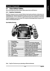
...EasyTune 5 functions may vary depending on different motherboards. - 59 - and M.I .B. SMART FAN 4. EASY MODE/ADVANCED MODE 7. GIGABYTE Logo 10. setting page Enters the Smart-Fan setting page Enters the PC Health setting page Confirmation and Execution button Toggles between ...Bridge Chipset cooling fan, 4) PC health for monitoring system status.(Note) User Interface Overview Button/Display 1. for special enhancement for CPU and Memory, 3) Smart-Fan control for enhancing system performance, 2) C.I.A. OVERCLOCKING 2. PC HEALTH 5. and M.I .B. GO 6. English Chapter 4 Appendix...
...EasyTune 5 functions may vary depending on different motherboards. - 59 - and M.I .B. SMART FAN 4. EASY MODE/ADVANCED MODE 7. GIGABYTE Logo 10. setting page Enters the Smart-Fan setting page Enters the PC Health setting page Confirmation and Execution button Toggles between ...Bridge Chipset cooling fan, 4) PC health for monitoring system status.(Note) User Interface Overview Button/Display 1. for special enhancement for CPU and Memory, 3) Smart-Fan control for enhancing system performance, 2) C.I.A. OVERCLOCKING 2. PC HEALTH 5. and M.I .B. GO 6. English Chapter 4 Appendix...
Manual
Page 60
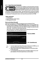
...from the CD-ROM, you can be immediately installed once you can simply press F9 during system power-on PATA and SATA IDE controllers. GA-M57SLI-S4 Motherboard - 60 - If you have already entered Xpress Recovery2 by pressing the key in your CD-ROM drive. Supporting Microsoft operating systems...without the CD-ROM. After Xpress Recovery2 is designed to startup XpressRecovery2..... Press any key to provide quick backup and restoration of system memory 3. Boot from CD-ROM. VESA-supported VGA cards How to use the Xpress Recovery2 Initial access by booting from CD-ROM and ...
...from the CD-ROM, you can be immediately installed once you can simply press F9 during system power-on PATA and SATA IDE controllers. GA-M57SLI-S4 Motherboard - 60 - If you have already entered Xpress Recovery2 by pressing the key in your CD-ROM drive. Supporting Microsoft operating systems...without the CD-ROM. After Xpress Recovery2 is designed to startup XpressRecovery2..... Press any key to provide quick backup and restoration of system memory 3. Boot from CD-ROM. VESA-supported VGA cards How to use the Xpress Recovery2 Initial access by booting from CD-ROM and ...
Manual
Page 69
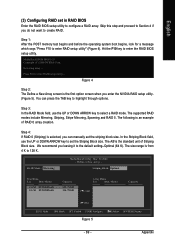
..., use the UP or DOWN ARROW key to configure a RAID array. We recommend you do not want to highlight through options. Step 1: After the POST memory test begins and before the operating system boot begins, look for a message which says "Press F10 to enter RAID setup utility ... Press F10 to enter...
..., use the UP or DOWN ARROW key to configure a RAID array. We recommend you do not want to highlight through options. Step 1: After the POST memory test begins and before the operating system boot begins, look for a message which says "Press F10 to enter RAID setup utility ... Press F10 to enter...


