Manual
Page 8
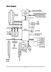
Block Diagram SLI PCIe CLK (100 MHz) AMD Socket AM2 CPU CPU CLK+/-(200 MHz) DDRII 800/667/533/400 MHz DIMM Hyper Transport Bus Dual Channel Memory PCI Express x8 PCI Express x16 Marvell 88E1116 LAN RJ45 PCI Express Bus x1 x1 x1 PCIe CLK (100 MHz) 3 PCI Express x1 PCI Bus TSB43AB23 3 IEEE 1394a nVIDIA® nForce 570-SLI BIOS 6 SATA 3Gb/s ATA-33/66/100/133 IDE Channel CODEC LPC BUS IT8716 Floppy LPT Port COM Port 10 USB Ports PS/2 KB/Mouse Surround Speaker Out Center/Subwoofer Speaker Out Side Speaker Out MIC Line-Out Line-In SPDIF In SPDIF Out 2 PCI PCI CLK (33 MHz) - 8 -
Block Diagram SLI PCIe CLK (100 MHz) AMD Socket AM2 CPU CPU CLK+/-(200 MHz) DDRII 800/667/533/400 MHz DIMM Hyper Transport Bus Dual Channel Memory PCI Express x8 PCI Express x16 Marvell 88E1116 LAN RJ45 PCI Express Bus x1 x1 x1 PCIe CLK (100 MHz) 3 PCI Express x1 PCI Bus TSB43AB23 3 IEEE 1394a nVIDIA® nForce 570-SLI BIOS 6 SATA 3Gb/s ATA-33/66/100/133 IDE Channel CODEC LPC BUS IT8716 Floppy LPT Port COM Port 10 USB Ports PS/2 KB/Mouse Surround Speaker Out Center/Subwoofer Speaker Out Side Speaker Out MIC Line-Out Line-In SPDIF In SPDIF Out 2 PCI PCI CLK (33 MHz) - 8 -
Manual
Page 10
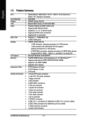
...667/533/400 DIMMs Š Supports 1.8V DDRII DIMMs Š Supports ECC memory Expanstion Slots Š 2 PCI Express x16 slots Š 3 PCI Express x1 slots Š 2 PCI slots Internal Connectors Š 1 24-pin ATX power connector Š 1 4-pin ATX 12V power connector Š... Š 3 USB 2.0/1.1 connectors for additional 6 USB 2.0/1.1 ports by cables Š 1 chassis intrusion connector Š 1 power LED connector GA-M57SLI-S4 Motherboard - 10 - English 1-2 Feature Summary CPU Š Socket AM2 for additional 2 ports by cables Š 2 IEEE 1394a connectors for AMD...
...667/533/400 DIMMs Š Supports 1.8V DDRII DIMMs Š Supports ECC memory Expanstion Slots Š 2 PCI Express x16 slots Š 3 PCI Express x1 slots Š 2 PCI slots Internal Connectors Š 1 24-pin ATX power connector Š 1 4-pin ATX 12V power connector Š... Š 3 USB 2.0/1.1 connectors for additional 6 USB 2.0/1.1 ports by cables Š 1 chassis intrusion connector Š 1 power LED connector GA-M57SLI-S4 Motherboard - 10 - English 1-2 Feature Summary CPU Š Socket AM2 for additional 2 ports by cables Š 2 IEEE 1394a connectors for AMD...

Manual
Page 16
...VGA card : Please carefully pull out the small white-drawable bar at the end of the drawable bar as the picture to the onboard PCI Express x16 slot. The motherboard includes a PCIE_12V power connector, which provides extra power to the left shows. English 1-5 Installation of the expansion card...6. For example: Installing a PCI Express x16 VGA card: To install the VGA card: Please align the VGA card with the PCI Express x16 slot and press down on the opposite side of the PCI Express x16 slot when you can also press the latch on the card. GA-M57SLI-S4 Motherboard - 16 - Install ...
...VGA card : Please carefully pull out the small white-drawable bar at the end of the drawable bar as the picture to the onboard PCI Express x16 slot. The motherboard includes a PCIE_12V power connector, which provides extra power to the left shows. English 1-5 Installation of the expansion card...6. For example: Installing a PCI Express x16 VGA card: To install the VGA card: Please align the VGA card with the PCI Express x16 slot and press down on the opposite side of the PCI Express x16 slot when you can also press the latch on the card. GA-M57SLI-S4 Motherboard - 16 - Install ...
Manual
Page 24
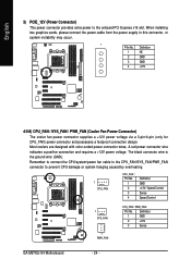
...occur. 1 PIin No. When installing two graphics cards, please connect the power cable from the power supply to the onboard PCI Express x16 slot. Remember to connect the CPU/system/power fan cable to the CPU_FAN/SYS_FAN/PWR_FAN connector to prevent CPU damage or ... power voltage via a 3-pin/4-pin (only for CPU_FAN) power connector and possesses a foolproof connection design. Definition 1 GND 2 +12V 3 Sense GA-M57SLI-S4 Motherboard - 24 - A red power connector wire indicates a positive connection and requires a +12V power voltage. The black connector wire is the ground wire (GND...
...occur. 1 PIin No. When installing two graphics cards, please connect the power cable from the power supply to the onboard PCI Express x16 slot. Remember to connect the CPU/system/power fan cable to the CPU_FAN/SYS_FAN/PWR_FAN connector to prevent CPU damage or ... power voltage via a 3-pin/4-pin (only for CPU_FAN) power connector and possesses a foolproof connection design. Definition 1 GND 2 +12V 3 Sense GA-M57SLI-S4 Motherboard - 24 - A red power connector wire indicates a positive connection and requires a +12V power voltage. The black connector wire is the ground wire (GND...

Manual
Page 39
...the monitor display from 720 KB, 1.2 MB or 1.44 MB drive type as they are all 80 tracks. If you install a PCI VGA card and a PCI Express VGA card on the motherboard. BIOS Setup Disabled BIOS will determine the floppy disk drive installed is 40 or 80 tracks. 360 KB ...warnings when thirdparty hardware monitor utility is 40 or 80 tracks. capability. Set Init Display First to PCI Express VGA card (the PCIE_16_1 slot). (Default value) PEG (Slot2) Set Init Display First to PCI VGA card. English Boot Up Floppy Seek During POST, BIOS will not search for floppy disk ...
...the monitor display from 720 KB, 1.2 MB or 1.44 MB drive type as they are all 80 tracks. If you install a PCI VGA card and a PCI Express VGA card on the motherboard. BIOS Setup Disabled BIOS will determine the floppy disk drive installed is 40 or 80 tracks. 360 KB ...warnings when thirdparty hardware monitor utility is 40 or 80 tracks. capability. Set Init Display First to PCI Express VGA card (the PCIE_16_1 slot). (Default value) PEG (Slot2) Set Init Display First to PCI VGA card. English Boot Up Floppy Seek During POST, BIOS will not search for floppy disk ...

Manual
Page 50
... by 0.025V to 0.375V. Normal sets the CPU voltage as chipset and PCIe required. (Default value) +0.025V ~ +0.375V Increase PCIe voltage by 0.025V to 0.375V. GA-M57SLI-S4 Motherboard - 50 - Normal Supply chipset and PCIe voltage as required. CPU HT-Link Voltage Sets the voltage settings for the memory. CPU Voltage Control Allows...-Link between CPU and chipset. Chipset/PCIE Voltage Sets the voltage settings for HT-Link. HT-Link Voltage Sets the voltage settings for chipset and PCI Express bus.
... by 0.025V to 0.375V. Normal sets the CPU voltage as chipset and PCIe required. (Default value) +0.025V ~ +0.375V Increase PCIe voltage by 0.025V to 0.375V. GA-M57SLI-S4 Motherboard - 50 - Normal Supply chipset and PCIe voltage as required. CPU HT-Link Voltage Sets the voltage settings for the memory. CPU Voltage Control Allows...-Link between CPU and chipset. Chipset/PCIE Voltage Sets the voltage settings for HT-Link. HT-Link Voltage Sets the voltage settings for chipset and PCI Express bus.


