User Manual
Page 1
GA-K8NSC-939 AMD Socket 939 Processor Motherboard User's Manual Rev. 1003 12ME-K8NSC939-1003
GA-K8NSC-939 AMD Socket 939 Processor Motherboard User's Manual Rev. 1003 12ME-K8NSC939-1003
User Manual
Page 2
Motherboard GA-K8NSC-939 Feb. 23, 2005 Motherboard GA-K8NSC-939 Feb. 23, 2005
Motherboard GA-K8NSC-939 Feb. 23, 2005 Motherboard GA-K8NSC-939 Feb. 23, 2005
User Manual
Page 4
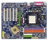
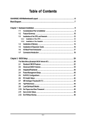
Table of Contents GA-K8NSC-939 Motherboard Layout 6 Block Diagram ...7 Chapter 1 Hardware Installation 9 1-1 Considerations Prior to Installation 9 1-2 Feature Summary 10 1-3 Installation of the CPU and Heatsink 12 1-3-1 Installation of the CPU ...
Table of Contents GA-K8NSC-939 Motherboard Layout 6 Block Diagram ...7 Chapter 1 Hardware Installation 9 1-1 Considerations Prior to Installation 9 1-2 Feature Summary 10 1-3 Installation of the CPU and Heatsink 12 1-3-1 Installation of the CPU ...

User Manual
Page 10
GA-K8NSC-939 Motherboard - 10 - For example, 4GB of memory size will instead be shown as 3.xxGB memory during system startup. (Note 2) To set up to standard PC ... 2) Š Supports Line In ; English 1-2 Feature Summary CPU Chipset Memory Slots IDE Connections FDD Connections Onboard SATA Peripherals Onboard LAN Onboard Audio I/O Control Š Socket 939 for system usage and therefore the actual memory size is reserved for AMD AthlonTM 64 / 64 FX processor (K8) Š 1600MT/s system bus Š Supports...
GA-K8NSC-939 Motherboard - 10 - For example, 4GB of memory size will instead be shown as 3.xxGB memory during system startup. (Note 2) To set up to standard PC ... 2) Š Supports Line In ; English 1-2 Feature Summary CPU Chipset Memory Slots IDE Connections FDD Connections Onboard SATA Peripherals Onboard LAN Onboard Audio I/O Control Š Socket 939 for system usage and therefore the actual memory size is reserved for AMD AthlonTM 64 / 64 FX processor (K8) Š 1600MT/s system bus Š Supports...
User Manual
Page 12
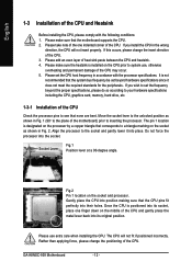
...-degree angle. Fig.2 Pin 1 location on the socket as shown in Fig. 1 (90o to the plane of the CPU. The CPU will not insert properly. GA-K8NSC-939 Motherboard - 12 - Move the socket lever to the unlocked position as shown in Fig. 2. Align the processor to see that the motherboard supports the CPU...
...-degree angle. Fig.2 Pin 1 location on the socket as shown in Fig. 1 (90o to the plane of the CPU. The CPU will not insert properly. GA-K8NSC-939 Motherboard - 12 - Move the socket lever to the unlocked position as shown in Fig. 2. Align the processor to see that the motherboard supports the CPU...
User Manual
Page 14
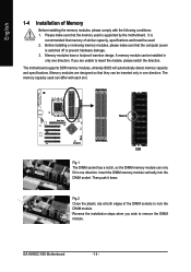
... brand be inserted only in one direction. English 1-4 Installation of Memory Before installing the memory modules, please comply with each slot. Then push it down. GA-K8NSC-939 Motherboard - 14 - It is recommended that they can differ with the following conditions: 1. Insert the DIMM memory module vertically into the DIMM socket. The motherboard...
... brand be inserted only in one direction. English 1-4 Installation of Memory Before installing the memory modules, please comply with each slot. Then push it down. GA-K8NSC-939 Motherboard - 14 - It is recommended that they can differ with the following conditions: 1. Insert the DIMM memory module vertically into the DIMM socket. The motherboard...
User Manual
Page 15
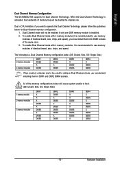
English Dual Channel Memory Configuration The GA-K8NSC-939 supports the Dual Channel Technology. To enable Dual Channel mode with 4 memory modules, it is recommended to achieve Dual Channel mode, we recommend installing them ...
English Dual Channel Memory Configuration The GA-K8NSC-939 supports the Dual Channel Technology. To enable Dual Channel mode with 4 memory modules, it is recommended to achieve Dual Channel mode, we recommend installing them ...
User Manual
Page 16
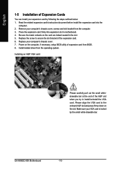
... pull out the small whitedrawable bar at the end of the AGP slot when you try to secure the slot bracket of the expansion card. 6. GA-K8NSC-939 Motherboard - 16 - Remove your computer's chassis cover, screws and slot bracket from the operating system. Replace your computer's chassis cover. 7. Please align the VGA card...
... pull out the small whitedrawable bar at the end of the AGP slot when you try to secure the slot bracket of the expansion card. 6. GA-K8NSC-939 Motherboard - 16 - Remove your computer's chassis cover, screws and slot bracket from the operating system. Replace your computer's chassis cover. 7. Please align the VGA card...

User Manual
Page 18
English 1-7 Connectors Introduction 13 8 7 11 12 13 16 14 1) ATX_12V 2) ATX (Power Connector) 3) CPU_FAN 4) SYS_FAN 5) NB_FAN 6) FDD 7) IDE1 / IDE2 8) SATA0_SB / SATA1_SB 9) PWR_LED 2 6 18 5 17 10 9 4 15 10) F_PANEL 11) F_AUDIO 12) CD_IN 13) SUR_CEN 14) SPDIF_IO 15) F_USB1 / F_USB2 16) IR_CIR 17) CLR_CMOS 18) BATTERY GA-K8NSC-939 Motherboard - 18 -
English 1-7 Connectors Introduction 13 8 7 11 12 13 16 14 1) ATX_12V 2) ATX (Power Connector) 3) CPU_FAN 4) SYS_FAN 5) NB_FAN 6) FDD 7) IDE1 / IDE2 8) SATA0_SB / SATA1_SB 9) PWR_LED 2 6 18 5 17 10 9 4 15 10) F_PANEL 11) F_AUDIO 12) CD_IN 13) SUR_CEN 14) SPDIF_IO 15) F_USB1 / F_USB2 16) IR_CIR 17) CLR_CMOS 18) BATTERY GA-K8NSC-939 Motherboard - 18 -
User Manual
Page 20
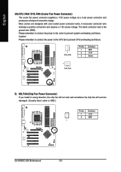
... connector supplies a +12V power voltage via a 3-pin power connector and possesses a foolproof connection design. The black connector wire is GND.) Pin No. Definition 1 +12V 2 GND 1 GA-K8NSC-939 Motherboard - 20 - Most coolers are designed with color-coded power connector wires. Caution! Please remember to connect the power to the cooler to prevent CPU...
... connector supplies a +12V power voltage via a 3-pin power connector and possesses a foolproof connection design. The black connector wire is GND.) Pin No. Definition 1 +12V 2 GND 1 GA-K8NSC-939 Motherboard - 20 - Most coolers are designed with color-coded power connector wires. Caution! Please remember to connect the power to the cooler to prevent CPU...
User Manual
Page 22
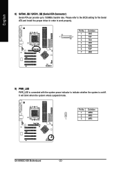
Definition 1 GND 1 7 2 TXP 3 TXN 4 GND 5 RXN 6 RXP 7 GND 9) PWR_LED PWR_LED is connected with the system power indicator to work properly. GA-K8NSC-939 Motherboard - 22 - Definition 1 MPD+ 2 MPD- 1 3 MPD- Please refer to the BIOS setting for the Serial ATA and install the proper driver in order to indicate whether the system is on/off. It will blink when the system enters suspend mode. Pin No. English 8) SATA0_SB / SATA1_SB (Serial ATA Connector) Serial ATA can provide up to 150MB/s transfer rate. Pin No.
Definition 1 GND 1 7 2 TXP 3 TXN 4 GND 5 RXN 6 RXP 7 GND 9) PWR_LED PWR_LED is connected with the system power indicator to work properly. GA-K8NSC-939 Motherboard - 22 - Definition 1 MPD+ 2 MPD- 1 3 MPD- Please refer to the BIOS setting for the Serial ATA and install the proper driver in order to indicate whether the system is on/off. It will blink when the system enters suspend mode. Pin No. English 8) SATA0_SB / SATA1_SB (Serial ATA Connector) Serial ATA can provide up to 150MB/s transfer rate. Pin No.
User Manual
Page 24
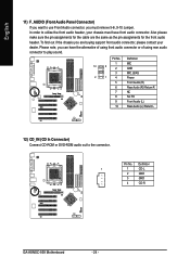
... the chassis you can have front audio connector. Also please make sure the pin assignments for the front audio header. Definition 1 1 CD-L 2 GND 3 GND 4 CD-R GA-K8NSC-939 Motherboard - 24 - Please note, you are the same as the pin assignments for the cable are buying support front audio connector, please contact your chassis...
... the chassis you can have front audio connector. Also please make sure the pin assignments for the front audio header. Definition 1 1 CD-L 2 GND 3 GND 4 CD-R GA-K8NSC-939 Motherboard - 24 - Please note, you are the same as the pin assignments for the cable are buying support front audio connector, please contact your chassis...
User Manual
Page 26
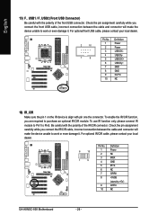
... USB cable, please contact your local dealer. 6 10 1 5 Pin No. 1 2 3 4 5 6 7 8 9 10 Definition Power NC IRRX GND IRTX NC CIRRX +5VSB (stand by +5V) CIRTX NC GA-K8NSC-939 Motherboard - 26 - To enable the IR/CIR function, you connect the IR/CIR cable, incorrect connection between the cable and connector will make the device...
... USB cable, please contact your local dealer. 6 10 1 5 Pin No. 1 2 3 4 5 6 7 8 9 10 Definition Power NC IRRX GND IRTX NC CIRRX +5VSB (stand by +5V) CIRTX NC GA-K8NSC-939 Motherboard - 26 - To enable the IR/CIR function, you connect the IR/CIR cable, incorrect connection between the cable and connector will make the device...
User Manual
Page 30
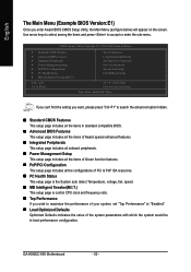
..., please press "Ctrl+F1" to search the advanced option hidden. „ Standard CMOS Features This setup page includes all the items in best performance configuration. GA-K8NSC-939 Motherboard - 30 - Use arrow keys to select among the items and press to "Enabled". „ Load Optimized Defaults Optimized Defaults indicates the value of the...
..., please press "Ctrl+F1" to search the advanced option hidden. „ Standard CMOS Features This setup page includes all the items in best performance configuration. GA-K8NSC-939 Motherboard - 30 - Use arrow keys to select among the items and press to "Enabled". „ Load Optimized Defaults Optimized Defaults indicates the value of the...

User Manual
Page 32
..." to select this if no SATA IDE devices are used and the system will skip the automatic detection step and allow for automatic device detection. GA-K8NSC-939 Motherboard - 32 - For example, 1 p.m. Week The week, from 1999 through 2098 Time The times format in . time clock. IDE Channel 0 Master/Slave; You can use...
..." to select this if no SATA IDE devices are used and the system will skip the automatic detection step and allow for automatic device detection. GA-K8NSC-939 Motherboard - 32 - For example, 1 p.m. Week The week, from 1999 through 2098 Time The times format in . time clock. IDE Channel 0 Master/Slave; You can use...
User Manual
Page 34
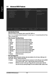
... they are all 80 tracks. USB-FDD USB-ZIP Select your boot device priority by USB-FDD. Press to move it is 360K. (Default value) GA-K8NSC-939 Motherboard - 34 - LS120 Hard Disk Select your boot device priority by LS120. Use < > or < > to select a device, then press to move it down the list...
... they are all 80 tracks. USB-FDD USB-ZIP Select your boot device priority by USB-FDD. Press to move it is 360K. (Default value) GA-K8NSC-939 Motherboard - 34 - LS120 Hard Disk Select your boot device priority by LS120. Use < > or < > to select a device, then press to move it down the list...

User Manual
Page 36
...] [Disabled] Item Help Menu Level` KLJI: Move Enter: Select +/-/PU/PD: Value F5: Previous Values F10: Save ESC: Exit F7: Optimized Defaults F1: General Help GA-K8NSC-939 Motherboard - 36 -
...] [Disabled] Item Help Menu Level` KLJI: Move Enter: Select +/-/PU/PD: Value F5: Previous Values F10: Save ESC: Exit F7: Optimized Defaults F1: General Help GA-K8NSC-939 Motherboard - 36 -
User Manual
Page 38
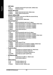
... value) 1 Set ECP Mode Use DMA to 1. English AC97 Audio Auto Autodetect onboard AC'97 audio function. (Default value) Disabled Disable this function. (Default value) GA-K8NSC-939 Motherboard - 38 - Enable onboard Serial port 1 and address is 3F8/IRQ4. (Default value) 2F8/IRQ3 Enable onboard Serial port 1 and address is 2F8/IRQ3. 3E8...
... value) 1 Set ECP Mode Use DMA to 1. English AC97 Audio Auto Autodetect onboard AC'97 audio function. (Default value) Disabled Disable this function. (Default value) GA-K8NSC-939 Motherboard - 38 - Enable onboard Serial port 1 and address is 3F8/IRQ4. (Default value) 2F8/IRQ3 Enable onboard Serial port 1 and address is 2F8/IRQ3. 3E8...
User Manual
Page 40
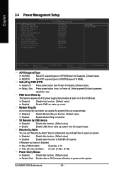
.... If Resume by USB device Disabled Disable this function. (Default value) Double Click Double click on PS/2 mouse left button to power on the system. GA-K8NSC-939 Motherboard - 40 - S3 Resume by Alarm is pressed less than 4 sec. Day of Month Alarm x Time (hh:mm:ss) Alarm Power On by Mouse Power...
.... If Resume by USB device Disabled Disable this function. (Default value) Double Click Double click on PS/2 mouse left button to power on the system. GA-K8NSC-939 Motherboard - 40 - S3 Resume by Alarm is pressed less than 4 sec. Day of Month Alarm x Time (hh:mm:ss) Alarm Power On by Mouse Power...

User Manual
Page 42
Current CPU/SYSTEM FAN Speed (RPM) Detect CPU/SYSTEM Fan speed status automatically. Monitor CPU temperature at 80oC / 176oF. Monitor CPU temperature at 70oC / 158oF. GA-K8NSC-939 Motherboard - 42 - English 2-6 PC Health Status CMOS Setup Utility-Copyright (C) 1984-2004 Award Software PC Health Status Vcore DDR25V +3.3V +12V Current CPU Temperature Current ...
Current CPU/SYSTEM FAN Speed (RPM) Detect CPU/SYSTEM Fan speed status automatically. Monitor CPU temperature at 80oC / 176oF. Monitor CPU temperature at 70oC / 158oF. GA-K8NSC-939 Motherboard - 42 - English 2-6 PC Health Status CMOS Setup Utility-Copyright (C) 1984-2004 Award Software PC Health Status Vcore DDR25V +3.3V +12V Current CPU Temperature Current ...
