
User Manual
Page 1
GA-K8N Ultra-SLI / GA-K8N Pro-SLI / GA-K8N-SLI AMD Socket 939 Processor Motherboard User's Manual Rev. 1004 12ME-K8NUSLI-1004
GA-K8N Ultra-SLI / GA-K8N Pro-SLI / GA-K8N-SLI AMD Socket 939 Processor Motherboard User's Manual Rev. 1004 12ME-K8NUSLI-1004
User Manual
Page 6
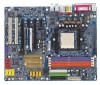
Table of Contents GA-K8N Ultra-SLI / GA-K8N Pro-SLI / GA-K8N-SLI Motherboard Layout 8 Block Diagram ...9 Chapter 1 Hardware Installation 11 1-1 Considerations Prior to Installation 11 1-2 Feature Summary 12 1-3 Installation of the CPU and Fan Heat Sink 14 1-3-1 ...
Table of Contents GA-K8N Ultra-SLI / GA-K8N Pro-SLI / GA-K8N-SLI Motherboard Layout 8 Block Diagram ...9 Chapter 1 Hardware Installation 11 1-1 Considerations Prior to Installation 11 1-2 Feature Summary 12 1-3 Installation of the CPU and Fan Heat Sink 14 1-3-1 ...
User Manual
Page 12
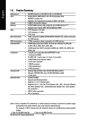
... Supports 2 / 4 / 6 / 8 channel audio Š Supports Line In ; Line Out (Front Speaker Out) ; Only for GA-K8N Ultra-SLI. MIC ; Only for GA-K8N Pro-SLI. Center/Subwoofer Speaker Out ; For example, 4 GB of memory is reserved for system usage and therefore the actual memory size is less ... 1-2 Feature Summary Motherboard CPU Chipset Memory Slots IDE Connections FDD Connections Onboard SATA Peripherals Onboard LAN Onboard Audio Š GA-K8N Ultra-SLI or GA-K8N Pro-SLI or GA-K8N-SLI Š Socket 939 for AMD AthlonTM 64 / 64 FX processor (K8) Š 2000MT/s system bus Š...
... Supports 2 / 4 / 6 / 8 channel audio Š Supports Line In ; Line Out (Front Speaker Out) ; Only for GA-K8N Ultra-SLI. MIC ; Only for GA-K8N Pro-SLI. Center/Subwoofer Speaker Out ; For example, 4 GB of memory is reserved for system usage and therefore the actual memory size is less ... 1-2 Feature Summary Motherboard CPU Chipset Memory Slots IDE Connections FDD Connections Onboard SATA Peripherals Onboard LAN Onboard Audio Š GA-K8N Ultra-SLI or GA-K8N Pro-SLI or GA-K8N-SLI Š Socket 939 for AMD AthlonTM 64 / 64 FX processor (K8) Š 2000MT/s system bus Š...
User Manual
Page 13
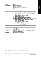
.../ PCI-E) ATX form factor; 30.5cm x 24.4cm (Note 2) EasyTune 5 functions may vary depending on different motherboards. Only for GA-K8N Ultra-SLI. supports data striping (RAID 0), mirroring (RAID 1), or striping + mirroring (RAID 0+1) - supports data striping (RAID 0), mirroring (RAID... RAID 5 - supports data transfer rate of 4 SATA 3Gb/s connections Onboard Silicon Image SiI3114 chip (SATA0_SII, SATA1_SII, SATA2_SII, SATA3_SII) - Only for GA-K8N Pro-SLI. - 13 - English I/O Control Š Hardware Monitor Š Š Š Š Š Š Onboard SATA RAID Š...
.../ PCI-E) ATX form factor; 30.5cm x 24.4cm (Note 2) EasyTune 5 functions may vary depending on different motherboards. Only for GA-K8N Ultra-SLI. supports data striping (RAID 0), mirroring (RAID 1), or striping + mirroring (RAID 0+1) - supports data striping (RAID 0), mirroring (RAID... RAID 5 - supports data transfer rate of 4 SATA 3Gb/s connections Onboard Silicon Image SiI3114 chip (SATA0_SII, SATA1_SII, SATA2_SII, SATA3_SII) - Only for GA-K8N Pro-SLI. - 13 - English I/O Control Š Hardware Monitor Š Š Š Š Š Š Onboard SATA RAID Š...
User Manual
Page 14
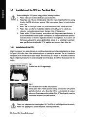
... and permanent damage of the CPU may occur. 5. The pin 1 location is positioned into its socket, place one indented corner of the CPU. K8 nForce4 SLI Series Motherboard - 14 - Socket lever Fig.1 Position lever at a 90 degree angle. English 1-3 Installation of the CPU and Fan Heat Sink Before installing the CPU...
... and permanent damage of the CPU may occur. 5. The pin 1 location is positioned into its socket, place one indented corner of the CPU. K8 nForce4 SLI Series Motherboard - 14 - Socket lever Fig.1 Position lever at a 90 degree angle. English 1-3 Installation of the CPU and Fan Heat Sink Before installing the CPU...

User Manual
Page 16
... has a notch, so the DIMM memory module can differ with the following conditions: 1. Memory modules have a foolproof insertion design. Then push it down. K8 nForce4 SLI Series Motherboard - 16 - English 1-4 Installation of Memory Before installing the memory modules, please comply with each slot. The motherboard supports DDR memory modules, whereby BIOS...
... has a notch, so the DIMM memory module can differ with the following conditions: 1. Memory modules have a foolproof insertion design. Then push it down. K8 nForce4 SLI Series Motherboard - 16 - English 1-4 Installation of Memory Before installing the memory modules, please comply with each slot. The motherboard supports DDR memory modules, whereby BIOS...

User Manual
Page 17
... Channel mode, we recommend installing them into DIMM sockets of the memory configurations below for Dual Channel memory configuration. 1. English Dual Channel Memory Configuration The GA-K8N Ultra-SLI/GA-K8N Pro-SLI/GA-K8N-SLI supports the Dual Channel Technology. Due to CPU limitation, if you want to use memory modules of identical brand, size, chips, and speed), you...
... Channel mode, we recommend installing them into DIMM sockets of the memory configurations below for Dual Channel memory configuration. 1. English Dual Channel Memory Configuration The GA-K8N Ultra-SLI/GA-K8N Pro-SLI/GA-K8N-SLI supports the Dual Channel Technology. Due to CPU limitation, if you want to use memory modules of identical brand, size, chips, and speed), you...
User Manual
Page 18
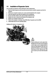
... to secure the slot bracket of the expansion card. 6. Press the expansion card firmly into the computer. 2. Install related driver from the computer. 3. K8 nForce4 SLI Series Motherboard - 18 - Please align the VGA card to the onboard PCI Express x 16 slot and press firmly down on the computer, if necessary, setup...
... to secure the slot bracket of the expansion card. 6. Press the expansion card firmly into the computer. 2. Install related driver from the computer. 3. K8 nForce4 SLI Series Motherboard - 18 - Please align the VGA card to the onboard PCI Express x 16 slot and press firmly down on the computer, if necessary, setup...

User Manual
Page 19
... NVIDIA GPU (graphics processing unit) and the NVIDIA nForce4 chipset. Before You Begin-- Understanding the GIGABYTE SLI switch module: You can find an SLI switch module socket inserted with the gold edge connector on the top and bottom of the same model... PCIE slots will depend on the GA-K8N Ulra-SLI/GA-K8N Pro-SLI/GA-K8N-SLI motherboard. The SLI design takes advantage of the increased bandwidth of SLI (Scalable Link Interface) Configuration NVIDIA nForce4 SLI offers blistering graphics performance with an SLI bridge connector to enable SLI function to bridge two NVIDIA SLIready ...
... NVIDIA GPU (graphics processing unit) and the NVIDIA nForce4 chipset. Before You Begin-- Understanding the GIGABYTE SLI switch module: You can find an SLI switch module socket inserted with the gold edge connector on the top and bottom of the same model... PCIE slots will depend on the GA-K8N Ulra-SLI/GA-K8N Pro-SLI/GA-K8N-SLI motherboard. The SLI design takes advantage of the increased bandwidth of SLI (Scalable Link Interface) Configuration NVIDIA nForce4 SLI offers blistering graphics performance with an SLI bridge connector to enable SLI function to bridge two NVIDIA SLIready ...
User Manual
Page 20
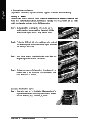
... out the module from the socket and insert it in the socket. Make sure the gold edge connectors are fully inserted. English III. Enabling SLI Mode-Follow the steps below to the PCIE_16_1 and PCIE_16_2 slots. Align the small notch at the top edge of the module above the socket.... Supported Operating Systems: Only Windows XP operating system is inserted in the socket in "1-5 Installation of Expansion Cards" on page 16 and install two SLI-ready graphics cards of the module until it away from the socket. Step 1: Gently spread the retaining clips of the module into the socket. Step...
... out the module from the socket and insert it in the socket. Make sure the gold edge connectors are fully inserted. English III. Enabling SLI Mode-Follow the steps below to the PCIE_16_1 and PCIE_16_2 slots. Align the small notch at the top edge of the module above the socket.... Supported Operating Systems: Only Windows XP operating system is inserted in the socket in "1-5 Installation of Expansion Cards" on page 16 and install two SLI-ready graphics cards of the module until it away from the socket. Step 1: Gently spread the retaining clips of the module into the socket. Step...

User Manual
Page 21
...installing graphics card driver in operating system, right-click the NVIDIA icon in BIOS Setup to PEG; English Step 2: Insert the SLI bridge (the GC-SLICON) to the SLI gold edge connector on top of both cards. retention bracket Step 4: Plug the display cable into either one of the bridge ...Gold edge connector on the PCIE_16_1 slot, make sure to set Init Display First to PEG(Slot2). System will appear. curely fit onto the SLI gold edge connetors of graphics card Step 3: In order to securely fix the bridge connector between the two cards, you plug the display cable...
...installing graphics card driver in operating system, right-click the NVIDIA icon in BIOS Setup to PEG; English Step 2: Insert the SLI bridge (the GC-SLICON) to the SLI gold edge connector on top of both cards. retention bracket Step 4: Plug the display cable into either one of the bridge ...Gold edge connector on the PCIE_16_1 slot, make sure to set Init Display First to PEG(Slot2). System will appear. curely fit onto the SLI gold edge connetors of graphics card Step 3: In order to securely fix the bridge connector between the two cards, you plug the display cable...

User Manual
Page 22
... your device has digital output function. Also make sure your OS does not support USB controller, please contact OS vendor for GA-K8N Ultra-SLI. can be connected to MIC In jack. K8 nForce4 SLI Series Motherboard - 22 - SPDIF_I (SPDIF In) Use SPDIF In feature only when your OS or device(s) vendors. LAN Port 1 The...
... your device has digital output function. Also make sure your OS does not support USB controller, please contact OS vendor for GA-K8N Ultra-SLI. can be connected to MIC In jack. K8 nForce4 SLI Series Motherboard - 22 - SPDIF_I (SPDIF In) Use SPDIF In feature only when your OS or device(s) vendors. LAN Port 1 The...
User Manual
Page 23
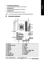
... audio functioning. 1-8 Connectors Introduction 13 8 11 13 1) ATX_12V 2) ATX (Power Connector) 3) CPU_FAN 4) SYS_FAN 5) PWR_FAN 6) NB_FAN 7) FDD 8) IDE1 / IDE2 9) S_ATA0/1/2/3_SB 10) SATA0/1/2/3_SII Only for GA-K8N Ultra-SLI. 2 5 7 19 6 18 9 12 14 4 15 17 10 16 11) F_AUDIO 12) F_PANEL 13) CD_IN 14) PWR_LED 15) IR/CIR 16) F_USB1 / F_USB2/F_USB3 17) F1_1394...
... audio functioning. 1-8 Connectors Introduction 13 8 11 13 1) ATX_12V 2) ATX (Power Connector) 3) CPU_FAN 4) SYS_FAN 5) PWR_FAN 6) NB_FAN 7) FDD 8) IDE1 / IDE2 9) S_ATA0/1/2/3_SB 10) SATA0/1/2/3_SII Only for GA-K8N Ultra-SLI. 2 5 7 19 6 18 9 12 14 4 15 17 10 16 11) F_AUDIO 12) F_PANEL 13) CD_IN 14) PWR_LED 15) IR/CIR 16) F_USB1 / F_USB2/F_USB3 17) F1_1394...
User Manual
Page 24
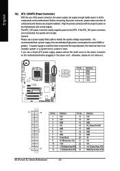
... 1 13 11 +12V(Onlyfor24-pinATX) 23 +5V (Only for 24-pin ATX) 12 3.3V(Onlyfor24-pinATX) 24 GND(Only for 24-pin ATX) K8 nForce4 SLI Series Motherboard - 24 - If a power supply is used (300W or greater). If you use of the power connector, the power supply can lead to all...
... 1 13 11 +12V(Onlyfor24-pinATX) 23 +5V (Only for 24-pin ATX) 12 3.3V(Onlyfor24-pinATX) 24 GND(Only for 24-pin ATX) K8 nForce4 SLI Series Motherboard - 24 - If a power supply is used (300W or greater). If you use of the power connector, the power supply can lead to all...
User Manual
Page 26
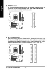
... connects to the FDD drive. If you wish to connect two IDE devices, please set the jumper on the IDE device). 40 39 2 1 K8 nForce4 SLI Series Motherboard - 26 - English 7) FDD (FDD Connector) The FDD connector is used to connect the FDD cable while the other as Master and the other...
... connects to the FDD drive. If you wish to connect two IDE devices, please set the jumper on the IDE device). 40 39 2 1 K8 nForce4 SLI Series Motherboard - 26 - English 7) FDD (FDD Connector) The FDD connector is used to connect the FDD cable while the other as Master and the other...
User Manual
Page 27
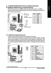
...pin assigment on the cable is the same as the pin assigment on the MB header. Please refer to the BIOS setting for GA-K8N Ultra-SLI. - 27 - In order to utilize the front audio header, your dealer. Hardware Installation English 9) S_ATA0/1/2/3_SB (SATA 3Gb/s Connectors, Controlled ...by nForce4 SLI) 10) SATA0/1/2/3_SII (SATA Connectors, Controlled by Sil3114) 11) F_AUDIO (Front Audio Panel Connector) If you want to use Front Audio connector...
...pin assigment on the cable is the same as the pin assigment on the MB header. Please refer to the BIOS setting for GA-K8N Ultra-SLI. - 27 - In order to utilize the front audio header, your dealer. Hardware Installation English 9) S_ATA0/1/2/3_SB (SATA 3Gb/s Connectors, Controlled ...by nForce4 SLI) 10) SATA0/1/2/3_SII (SATA Connectors, Controlled by Sil3114) 11) F_AUDIO (Front Audio Panel Connector) If you want to use Front Audio connector...
User Manual
Page 28
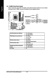
.... Pin 3: NC Pin 4: Data(-) Open: Normal Close: Reset Hardware System Open: Normal Close: Power On/Off Pin 1: LED anode(+) Pin 2: LED cathode(-) NC K8 nForce4 SLI Series Motherboard - 28 -
.... Pin 3: NC Pin 4: Data(-) Open: Normal Close: Reset Hardware System Open: Normal Close: Power On/Off Pin 1: LED anode(+) Pin 2: LED cathode(-) NC K8 nForce4 SLI Series Motherboard - 28 -
User Manual
Page 30
..., please contact your local dealer. 2 10 1 9 Pin No. 1 2 3 4 5 6 7 8 9 10 Definition Power Power USB DXUSB DyUSB DX+ USB Dy+ GND GND No Pin NC K8 nForce4 SLI Series Motherboard - 30 - To enable the IR/CIR function, you are required to Pin5.
..., please contact your local dealer. 2 10 1 9 Pin No. 1 2 3 4 5 6 7 8 9 10 Definition Power Power USB DXUSB DyUSB DX+ USB Dy+ GND GND No Pin NC K8 nForce4 SLI Series Motherboard - 30 - To enable the IR/CIR function, you are required to Pin5.
User Manual
Page 31
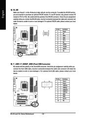
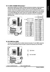
Only for GA-K8N Ultra-SLI. Be careful with the polarity of this header. For optional IEEE1394 cable, please contact your local dealer. Open: Normal 1 Short: Clear CMOS 1 Only for GA-K8N Pro-SLI. - 31 - To clear CMOS, temporarily short 1-2 pin. English 17) F1_1394/F2_1394 (IEEE 1394 Connectors) Serial interface standard set by this header. Default doesn't include...
Only for GA-K8N Ultra-SLI. Be careful with the polarity of this header. For optional IEEE1394 cable, please contact your local dealer. Open: Normal 1 Short: Clear CMOS 1 Only for GA-K8N Pro-SLI. - 31 - To clear CMOS, temporarily short 1-2 pin. English 17) F1_1394/F2_1394 (IEEE 1394 Connectors) Serial interface standard set by this header. Default doesn't include...
User Manual
Page 32
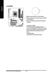
Plug the power cord and turn ON the computer. Turn OFF the computer and unplug the power cord. 2. K8 nForce4 SLI Series Motherboard - 32 - Re-install the battery. 4. Take out the battery gently and put it aside for about 10 minutes. (Or you want to makethem ...
Plug the power cord and turn ON the computer. Turn OFF the computer and unplug the power cord. 2. K8 nForce4 SLI Series Motherboard - 32 - Re-install the battery. 4. Take out the battery gently and put it aside for about 10 minutes. (Or you want to makethem ...


