
Manual
Page 7
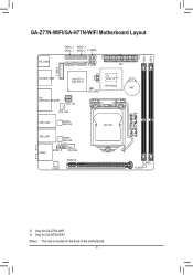
DDR3_1 DDR3_2 GA-Z77N-WIFI/GA-H77N-WIFI Motherboard Layout SATA3_0 SATA2_3 SATA3_1 SATA2_2 F_PANEL KB_USB30 F_USB1 ATX F_USB30 DOUBLE_HDMI Intel® Z77 j Intel® H77 k COM iTE Super I/O (Note) WIFI Module BAT CLR_CMOS DVI ANTENNA_BRACKET ATX_12V SYS_FAN USB_LAN2 Realtek GbE LAN LGA1155 GA-Z77N-WIFI GA-H77N-WIFI USB_LAN1 Realtek GbE LAN F_AUDIO AUDIO SPDIF_O CPU_FAN PCIEX16 CODEC M_BIOS B_BIOS MM Only for GA-H77N-WIFI. (Note) The chip is located on the back of the motherboard. - 7 - NN Only for GA-Z77N-WIFI.
DDR3_1 DDR3_2 GA-Z77N-WIFI/GA-H77N-WIFI Motherboard Layout SATA3_0 SATA2_3 SATA3_1 SATA2_2 F_PANEL KB_USB30 F_USB1 ATX F_USB30 DOUBLE_HDMI Intel® Z77 j Intel® H77 k COM iTE Super I/O (Note) WIFI Module BAT CLR_CMOS DVI ANTENNA_BRACKET ATX_12V SYS_FAN USB_LAN2 Realtek GbE LAN LGA1155 GA-Z77N-WIFI GA-H77N-WIFI USB_LAN1 Realtek GbE LAN F_AUDIO AUDIO SPDIF_O CPU_FAN PCIEX16 CODEC M_BIOS B_BIOS MM Only for GA-H77N-WIFI. (Note) The chip is located on the back of the motherboard. - 7 - NN Only for GA-Z77N-WIFI.
Manual
Page 8
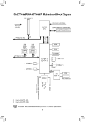
GA-Z77N-WIFI/GA-H77N-WIFI Motherboard Block Diagram 1 PCI Express x16 PCIe CLK (100 MHz) LGA1155 CPU CPU CLK+/- (100 MHz) DDR3 1600/1333/1066/800 MHz Dual Channel Memory DMI Interface FDI Interface PCI Express Bus x16 LAN RJ45 Realtek ... LPC Bus iTE Super I/O COM PS/2 KB/Mouse Rear Speaker Out Center/Subwoofer Speaker Out MIC Line Out Line In S/PDIF Out MM Only for GA-H77N-WIFI. For detailed product information/limitation(s), refer to "1-2 Product Specifications." - 8 - NN Only for...
GA-Z77N-WIFI/GA-H77N-WIFI Motherboard Block Diagram 1 PCI Express x16 PCIe CLK (100 MHz) LGA1155 CPU CPU CLK+/- (100 MHz) DDR3 1600/1333/1066/800 MHz Dual Channel Memory DMI Interface FDI Interface PCI Express Bus x16 LAN RJ45 Realtek ... LPC Bus iTE Super I/O COM PS/2 KB/Mouse Rear Speaker Out Center/Subwoofer Speaker Out MIC Line Out Line In S/PDIF Out MM Only for GA-H77N-WIFI. For detailed product information/limitation(s), refer to "1-2 Product Specifications." - 8 - NN Only for...
Manual
Page 10
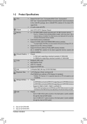
..., 2 ports available through the internal USB header) MM Only for GA-Z77N-WIFI. k ŠŠ Support for non-ECC memory modules ŠŠ Support for Extreme Memory Profile (XMP) memory modules (Go to GIGABYTE's website for the latest supported memory speeds and memory modules.) Onboard ... the LGA1155 package (Go to GIGABYTE's website for the latest CPU support list.) ŠŠ L3 cache varies with CPU Chipset ŠŠ Intel® Z77j/H77k Express Chipset Memory ŠŠ 2 x 1.5V DDR3 DIMM sockets supporting up to 2 SATA 3Gb/s devices - NN Only for GA-H77N-WIFI.
..., 2 ports available through the internal USB header) MM Only for GA-Z77N-WIFI. k ŠŠ Support for non-ECC memory modules ŠŠ Support for Extreme Memory Profile (XMP) memory modules (Go to GIGABYTE's website for the latest supported memory speeds and memory modules.) Onboard ... the LGA1155 package (Go to GIGABYTE's website for the latest CPU support list.) ŠŠ L3 cache varies with CPU Chipset ŠŠ Intel® Z77j/H77k Express Chipset Memory ŠŠ 2 x 1.5V DDR3 DIMM sockets supporting up to 2 SATA 3Gb/s devices - NN Only for GA-H77N-WIFI.

Manual
Page 13
... CPU socket and the notches on the computer if the CPU cooler is not recommended that the motherboard supports the CPU. (Go to GIGABYTE's website for the peripherals. It is not installed, otherwise overheating and damage of the CPU may locate the notches on both sides of...8226; Always turn on the CPU. If you may occur. •• Set the CPU host frequency in accordance with the CPU specifications. LGA1155 CPU Socket Alignment Key Alignment Key Pin One Corner of the CPU. Hardware Installation 1-3 Installing the CPU and CPU Cooler Read the following guidelines ...
... CPU socket and the notches on the computer if the CPU cooler is not recommended that the motherboard supports the CPU. (Go to GIGABYTE's website for the peripherals. It is not installed, otherwise overheating and damage of the CPU may locate the notches on both sides of...8226; Always turn on the CPU. If you may occur. •• Set the CPU host frequency in accordance with the CPU specifications. LGA1155 CPU Socket Alignment Key Alignment Key Pin One Corner of the CPU. Hardware Installation 1-3 Installing the CPU and CPU Cooler Read the following guidelines ...
