
Manual
Page 7
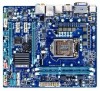
GA-H67MA-D2H-B3 Motherboard Layout KB_USB ATX_12V VGA_DVI LGA1155 PHASE LED HDMI_SPDIF USB_ESATA ATX USB30_LAN Renesas D720200 AUDIO CPU_FAN PCIEX16 GA-H67MA-D2H-B3 B_BIOS M_BIOS DDR3_1 DDR3_2 Realtek RTL8111E PCIEX1_1 PCIEX1_2 SYS_FAN CODEC PCIEX4 SPDIF_O BAT iTE IT8728 CLR_CMOS Intel® H67 SATA3_0 SATA3_1 SATA2_2 F_PANEL SATA2_3 SATA2_4 F_AUDIO COM F_USB4 F_USB2 F_USB3 F_USB1 - 7 -
GA-H67MA-D2H-B3 Motherboard Layout KB_USB ATX_12V VGA_DVI LGA1155 PHASE LED HDMI_SPDIF USB_ESATA ATX USB30_LAN Renesas D720200 AUDIO CPU_FAN PCIEX16 GA-H67MA-D2H-B3 B_BIOS M_BIOS DDR3_1 DDR3_2 Realtek RTL8111E PCIEX1_1 PCIEX1_2 SYS_FAN CODEC PCIEX4 SPDIF_O BAT iTE IT8728 CLR_CMOS Intel® H67 SATA3_0 SATA3_1 SATA2_2 F_PANEL SATA2_3 SATA2_4 F_AUDIO COM F_USB4 F_USB2 F_USB3 F_USB1 - 7 -

Manual
Page 8
GA-H67MA-D2H-B3 Motherboard Block Diagram 1 PCI Express x16 PCIe CLK (100 MHz) LGA1155 CPU CPU CLK+/- (100 MHz) DDR3 1333/1066/800 MHz Dual Channel Memory PCI Express Bus x16 LAN 2 USB 3.0/2.0 RJ45 Realtek RTL8111E Renesas D720200 PCI Express Bus x1 x1 x1 x4 Intel® H67 2 PCI Express x1 1 PCI Express x4 DMI Interface FDI Interface HDMI DVI-D D-Sub Dual BIOS 2 SATA 6Gb/s 4 SATA 3Gb/s 12 USB 2.0/1.1 CODEC LPC Bus iTE IT8728 COM PS/2 KB/Mouse Surround Speaker Out Center/Subwoofer Speaker Out Side Speaker Out MIC Line Out Line In S/PDIF Out - 8 -
GA-H67MA-D2H-B3 Motherboard Block Diagram 1 PCI Express x16 PCIe CLK (100 MHz) LGA1155 CPU CPU CLK+/- (100 MHz) DDR3 1333/1066/800 MHz Dual Channel Memory PCI Express Bus x16 LAN 2 USB 3.0/2.0 RJ45 Realtek RTL8111E Renesas D720200 PCI Express Bus x1 x1 x1 x4 Intel® H67 2 PCI Express x1 1 PCI Express x4 DMI Interface FDI Interface HDMI DVI-D D-Sub Dual BIOS 2 SATA 6Gb/s 4 SATA 3Gb/s 12 USB 2.0/1.1 CODEC LPC Bus iTE IT8728 COM PS/2 KB/Mouse Surround Speaker Out Center/Subwoofer Speaker Out Side Speaker Out MIC Line Out Line In S/PDIF Out - 8 -

Manual
Page 10
...Express 2.0 standard.) Multi-Graphics Support for the latest CPU support list L3 cache varies with CPU Chipset Intel® H67 Express Chipset Memory w Onboard Graphics Audio 2 x 1.5V DDR3 DIMM...3Gb/s device - Dual channel memory architecture Support for DDR3 1333/1066/800 MHz memory modules Support for non-ECC memory modules (Go to GIGABYTE's website for the latest supported memory speeds and memory modules.) Integrated in the Chipset: - 1 x D-Sub port - 1 x DVI...
...Express 2.0 standard.) Multi-Graphics Support for the latest CPU support list L3 cache varies with CPU Chipset Intel® H67 Express Chipset Memory w Onboard Graphics Audio 2 x 1.5V DDR3 DIMM...3Gb/s device - Dual channel memory architecture Support for DDR3 1333/1066/800 MHz memory modules Support for non-ECC memory modules (Go to GIGABYTE's website for the latest supported memory speeds and memory modules.) Integrated in the Chipset: - 1 x D-Sub port - 1 x DVI...

Manual
Page 20
... panel connector, first remove the cable from your device and then remove it from the connector. Rear Speaker Out Jack (Black) Use this jack. The H67 Chipset supports RAID function. Use the port to this audio jack to connect rear speakers in Chapter 5, "Configuring 2/4/5.1/7.1-Channel Audio." • When removing the cable...
... panel connector, first remove the cable from your device and then remove it from the connector. Rear Speaker Out Jack (Black) Use this jack. The H67 Chipset supports RAID function. Use the port to this audio jack to connect rear speakers in Chapter 5, "Configuring 2/4/5.1/7.1-Channel Audio." • When removing the cable...

Manual
Page 23
... and system from overheating. Most fan headers possess a foolproof insertion design. Do not place a jumper cap on the headers. 5) SATA3_0/1 (SATA 6Gb/s Connectors, Controlled by H67 Chipset) The SATA connectors conform to SATA 6Gb/s standard and are compatible with the SATA2_2/3/4 and eSATA connectors . (Note) Refer to be implemented on the...
... and system from overheating. Most fan headers possess a foolproof insertion design. Do not place a jumper cap on the headers. 5) SATA3_0/1 (SATA 6Gb/s Connectors, Controlled by H67 Chipset) The SATA connectors conform to SATA 6Gb/s standard and are compatible with the SATA2_2/3/4 and eSATA connectors . (Note) Refer to be implemented on the...

Manual
Page 24
...or may clear the CMOS values by removing the battery: 1. DEBUG PORT DEBUG PORT DEBUG PORT 6) SATA2_2/3/4 (SATA 3Gb/s Connectors, Controlled by H67 Chipset) The SATA connectors conform to keep the values (such as BIOS configurations, date, and time information) in the CMOS when the computer is...may be an even number. • A RAID 5 configuration requires at least two hard drives. Danger of explosion if the battery is turned off. The H67 Chipset supports RAID 0, RAID 1, RAID 5, and RAID 10. Turn off your computer and unplug the power cord. 2. Each SATA connector supports a single ...
...or may clear the CMOS values by removing the battery: 1. DEBUG PORT DEBUG PORT DEBUG PORT 6) SATA2_2/3/4 (SATA 3Gb/s Connectors, Controlled by H67 Chipset) The SATA connectors conform to keep the values (such as BIOS configurations, date, and time information) in the CMOS when the computer is...may be an even number. • A RAID 5 configuration requires at least two hard drives. Danger of explosion if the battery is turned off. The H67 Chipset supports RAID 0, RAID 1, RAID 5, and RAID 10. Turn off your computer and unplug the power cord. 2. Each SATA connector supports a single ...

Manual
Page 30
... the first boot device, then press to access the Q-Flash utility directly without entering BIOS Setup. Motherboard Model BIOS Version H67MA-D2H-B3 F7b . . . . : BIOS Setup : XpressRecovery2 : Boot Menu : Qflash 12/28/2010-H67-7A89UG0AC-00 Function Keys SATA Mode Message: "SATA is set to Chapter 4, "Xpress Recovery2." : BOOT MENU Boot Menu allows you...
... the first boot device, then press to access the Q-Flash utility directly without entering BIOS Setup. Motherboard Model BIOS Version H67MA-D2H-B3 F7b . . . . : BIOS Setup : XpressRecovery2 : Boot Menu : Qflash 12/28/2010-H67-7A89UG0AC-00 Function Keys SATA Mode Message: "SATA is set to Chapter 4, "Xpress Recovery2." : BOOT MENU Boot Menu allows you...
Manual
Page 45
... item below . When set to RAID(XHD) automatically. For details on using the GIGABYTE X.H.D utility, refer to Chaper 4, "eXtreme Hard Drive (X.H.D)." (Default: Disabled) PCH SATA Control Mode (Intel H67 Chipset) Enables or disables RAID for the SATA controllers integrated in Native IDE mode. IDE...IDE mode. (Default) RAID(XHD) Enables RAID for the SATA controllers. Enabled Allows the SATA controllers to operate in the Intel H67 Chipset. Enable Native IDE mode if you wish to AHCI mode. BIOS Setup 2-6 Integrated Peripherals CMOS Setup Utility-Copyright (C) 1984-2010...
... item below . When set to RAID(XHD) automatically. For details on using the GIGABYTE X.H.D utility, refer to Chaper 4, "eXtreme Hard Drive (X.H.D)." (Default: Disabled) PCH SATA Control Mode (Intel H67 Chipset) Enables or disables RAID for the SATA controllers integrated in Native IDE mode. IDE...IDE mode. (Default) RAID(XHD) Enables RAID for the SATA controllers. Enabled Allows the SATA controllers to operate in the Intel H67 Chipset. Enable Native IDE mode if you wish to AHCI mode. BIOS Setup 2-6 Integrated Peripherals CMOS Setup Utility-Copyright (C) 1984-2010...

Manual
Page 62
... the POST, press the key to a hard drive in the Windows environment. @BIOS will take over on the main BIOS. 4-2 BIOS Update Utilities GIGABYTE motherboards provide two unique BIOS update tools, Q-Flash™ and @BIOS™. H67MAD2H.F1) to your computer by either pressing the key during the ...the key during the POST or pressing the key in BIOS Setup. Award Modular BIOS v6.00PG Copyright (C) 1984-2010, Award Software, Inc. H67MA-D2H-B3 F7b . . . . : BIOS Setup : XpressRecovery2 : Boot Menu : Qflash 12/28/2010-H67-7A89UG0AC-00 Because BIOS flashing is saved to enter Q-Flash.
... the POST, press the key to a hard drive in the Windows environment. @BIOS will take over on the main BIOS. 4-2 BIOS Update Utilities GIGABYTE motherboards provide two unique BIOS update tools, Q-Flash™ and @BIOS™. H67MAD2H.F1) to your computer by either pressing the key during the ...the key during the POST or pressing the key in BIOS Setup. Award Modular BIOS v6.00PG Copyright (C) 1984-2010, Award Software, Inc. H67MA-D2H-B3 F7b . . . . : BIOS Setup : XpressRecovery2 : Boot Menu : Qflash 12/28/2010-H67-7A89UG0AC-00 Because BIOS flashing is saved to enter Q-Flash.

Manual
Page 85
...(R) Desktop/Workstation/Server Express Chipset SATA AHCI Controller item and press . Refer to the following for the location of the driver. • For the Intel H67, copy all required drivers from the motherboard driver disk to install separate RAID/AHCI driver during the Windows installation process. Step 2: Insert the floppy disk...
...(R) Desktop/Workstation/Server Express Chipset SATA AHCI Controller item and press . Refer to the following for the location of the driver. • For the Intel H67, copy all required drivers from the motherboard driver disk to install separate RAID/AHCI driver during the Windows installation process. Step 2: Insert the floppy disk...