
Manual
Page 1
GA-H67MA-D2H-B3 LGA1155 socket motherboard for Intel® Core™ i7 processors/ Intel® Core™ i5 processors/Intel® Core™ i3 processors/ Intel® Pentium® processors/Intel® Celeron® processors User's Manual Rev. 1101 12ME-H67D2HB-1101R
GA-H67MA-D2H-B3 LGA1155 socket motherboard for Intel® Core™ i7 processors/ Intel® Core™ i5 processors/Intel® Core™ i3 processors/ Intel® Pentium® processors/Intel® Celeron® processors User's Manual Rev. 1101 12ME-H67D2HB-1101R

Manual
Page 7
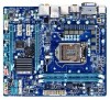
GA-H67MA-D2H-B3 Motherboard Layout KB_USB ATX_12V VGA_DVI LGA1155 PHASE LED HDMI_SPDIF USB_ESATA ATX USB30_LAN Renesas D720200 AUDIO CPU_FAN PCIEX16 GA-H67MA-D2H-B3 B_BIOS M_BIOS DDR3_1 DDR3_2 Realtek RTL8111E PCIEX1_1 PCIEX1_2 SYS_FAN CODEC PCIEX4 SPDIF_O BAT iTE IT8728 CLR_CMOS Intel® H67 SATA3_0 SATA3_1 SATA2_2 F_PANEL SATA2_3 SATA2_4 F_AUDIO COM F_USB4 F_USB2 F_USB3 F_USB1 - 7 -
GA-H67MA-D2H-B3 Motherboard Layout KB_USB ATX_12V VGA_DVI LGA1155 PHASE LED HDMI_SPDIF USB_ESATA ATX USB30_LAN Renesas D720200 AUDIO CPU_FAN PCIEX16 GA-H67MA-D2H-B3 B_BIOS M_BIOS DDR3_1 DDR3_2 Realtek RTL8111E PCIEX1_1 PCIEX1_2 SYS_FAN CODEC PCIEX4 SPDIF_O BAT iTE IT8728 CLR_CMOS Intel® H67 SATA3_0 SATA3_1 SATA2_2 F_PANEL SATA2_3 SATA2_4 F_AUDIO COM F_USB4 F_USB2 F_USB3 F_USB1 - 7 -

Manual
Page 8
GA-H67MA-D2H-B3 Motherboard Block Diagram 1 PCI Express x16 PCIe CLK (100 MHz) LGA1155 CPU CPU CLK+/- (100 MHz) DDR3 1333/1066/800 MHz Dual Channel Memory PCI Express Bus x16 LAN 2 USB 3.0/2.0 RJ45 Realtek RTL8111E Renesas D720200 PCI Express Bus x1 x1 x1 x4 Intel® H67 2 PCI Express x1 1 PCI Express x4 DMI Interface FDI Interface HDMI DVI-D D-Sub Dual BIOS 2 SATA 6Gb/s 4 SATA 3Gb/s 12 USB 2.0/1.1 CODEC LPC Bus iTE IT8728 COM PS/2 KB/Mouse Surround Speaker Out Center/Subwoofer Speaker Out Side Speaker Out MIC Line Out Line In S/PDIF Out - 8 -
GA-H67MA-D2H-B3 Motherboard Block Diagram 1 PCI Express x16 PCIe CLK (100 MHz) LGA1155 CPU CPU CLK+/- (100 MHz) DDR3 1333/1066/800 MHz Dual Channel Memory PCI Express Bus x16 LAN 2 USB 3.0/2.0 RJ45 Realtek RTL8111E Renesas D720200 PCI Express Bus x1 x1 x1 x4 Intel® H67 2 PCI Express x1 1 PCI Express x4 DMI Interface FDI Interface HDMI DVI-D D-Sub Dual BIOS 2 SATA 6Gb/s 4 SATA 3Gb/s 12 USB 2.0/1.1 CODEC LPC Bus iTE IT8728 COM PS/2 KB/Mouse Surround Speaker Out Center/Subwoofer Speaker Out Side Speaker Out MIC Line Out Line In S/PDIF Out - 8 -

Manual
Page 10
...2 x SATA 6Gb/s connectors (SATA3_0~SATA3_1) supporting up to 2 SATA 6Gb/s devices - 3 x SATA 3Gb/s connectors (SATA2_2~SATA2_4) supporting up to GIGABYTE's website for the latest supported memory speeds and memory modules.) Integrated in the PCIEX16 slot. 1 x PCI Express x16 slot, running at x4 ... performance, if only one PCI Express graphics card is to be installed, be less than 4 GB. sors in the LGA1155 package (Go to GIGABYTE's website for the latest CPU support list L3 cache varies with CPU Chipset Intel® H67 Express Chipset Memory...
...2 x SATA 6Gb/s connectors (SATA3_0~SATA3_1) supporting up to 2 SATA 6Gb/s devices - 3 x SATA 3Gb/s connectors (SATA2_2~SATA2_4) supporting up to GIGABYTE's website for the latest supported memory speeds and memory modules.) Integrated in the PCIEX16 slot. 1 x PCI Express x16 slot, running at x4 ... performance, if only one PCI Express graphics card is to be installed, be less than 4 GB. sors in the LGA1155 package (Go to GIGABYTE's website for the latest CPU support list L3 cache varies with CPU Chipset Intel® H67 Express Chipset Memory...

Manual
Page 13
Locate the alignment keys on the motherboard CPU socket and the notches on the CPU - 13 - LGA1155 CPU Socket Alignment Key Alignment Key Pin One Corner of the CPU Socket LGA1155 CPU Notch Notch Triangle Pin One Marking on the CPU. It is not installed, otherwise overheating and dam-...the CPU. • Do not turn on the computer if the CPU cooler is not recommended that the motherboard supports the CPU. (Go to GIGABYTE's website for the peripherals. If you may occur. • Set the CPU host frequency in accordance with the CPU specifications. Hardware Installation 1-3 ...
Locate the alignment keys on the motherboard CPU socket and the notches on the CPU - 13 - LGA1155 CPU Socket Alignment Key Alignment Key Pin One Corner of the CPU Socket LGA1155 CPU Notch Notch Triangle Pin One Marking on the CPU. It is not installed, otherwise overheating and dam-...the CPU. • Do not turn on the computer if the CPU cooler is not recommended that the motherboard supports the CPU. (Go to GIGABYTE's website for the peripherals. If you may occur. • Set the CPU host frequency in accordance with the CPU specifications. Hardware Installation 1-3 ...
