
Manual
Page 4
Table of Contents Box Contents...6 Optional Items...6 GA-H67A-UD3H-B3 Motherboard Layout 7 GA-H67A-UD3H-B3 Motherboard Block Diagram 8 Chapter 1 Hardware Installation 9 1-1 Installation Precautions 9 1-2 Product Specifications 10 1-3 Installing the CPU and CPU Cooler 13 1-3-1 Installing the CPU 13 1-3-2 Installing the CPU Cooler 15 1-4 Installing the Memory 16 1-4-1 Dual Channel Memory Configuration 16 1-4-2 Installing a Memory 17 1-5 Installing an Expansion Card 18 1-6 Back...
Table of Contents Box Contents...6 Optional Items...6 GA-H67A-UD3H-B3 Motherboard Layout 7 GA-H67A-UD3H-B3 Motherboard Block Diagram 8 Chapter 1 Hardware Installation 9 1-1 Installation Precautions 9 1-2 Product Specifications 10 1-3 Installing the CPU and CPU Cooler 13 1-3-1 Installing the CPU 13 1-3-2 Installing the CPU Cooler 15 1-4 Installing the Memory 16 1-4-1 Dual Channel Memory Configuration 16 1-4-2 Installing a Memory 17 1-5 Installing an Expansion Card 18 1-6 Back...

Manual
Page 8
GA-H67A-UD3H-B3 Motherboard Block Diagram 1 PCI Express x16 PCIe CLK (100 MHz) LGA1155 CPU CPU CLK+/- (100 MHz) DDR3 1333/1066/800 MHz Dual Channel Memory PCI Express Bus x16 1 PCI Express x4 2 PCI Express x1 or 2 USB 3.0/2.0 x4 x1 Renesas D720200 Switch PCI Express Bus x1 x1 x1 x1 Realtek ...
GA-H67A-UD3H-B3 Motherboard Block Diagram 1 PCI Express x16 PCIe CLK (100 MHz) LGA1155 CPU CPU CLK+/- (100 MHz) DDR3 1333/1066/800 MHz Dual Channel Memory PCI Express Bus x16 1 PCI Express x4 2 PCI Express x1 or 2 USB 3.0/2.0 x4 x1 Renesas D720200 Switch PCI Express Bus x1 x1 x1 x1 Realtek ...

Manual
Page 9
... allow screws to come in a high-temperature environment. • Turning on the computer power during the installation process can become damaged as a motherboard, CPU or memory. If you are connected tightly and securely. • When handling the motherboard, avoid touching any installation steps or have it on top of an antistatic...
... allow screws to come in a high-temperature environment. • Turning on the computer power during the installation process can become damaged as a motherboard, CPU or memory. If you are connected tightly and securely. • When handling the motherboard, avoid touching any installation steps or have it on top of an antistatic...

Manual
Page 10
... 4 GB. Dual channel memory architecture Support for DDR3 1333/1066/800 MHz memory modules Support for non-ECC memory modules (Go to GIGABYTE's website for the latest supported memory speeds and memory modules.) Integrated in the LGA1155 package (Go to GIGABYTE's website for Intel®...operates at x4 (PCIEX4) * The PCIEX4 slot shares bandwidth with CPU Chipset Intel® H67 Express Chipset Memory w Onboard Graphics Audio w 4 x 1.5V DDR3 DIMM sockets supporting up to...
... 4 GB. Dual channel memory architecture Support for DDR3 1333/1066/800 MHz memory modules Support for non-ECC memory modules (Go to GIGABYTE's website for the latest supported memory speeds and memory modules.) Integrated in the LGA1155 package (Go to GIGABYTE's website for Intel®...operates at x4 (PCIEX4) * The PCIEX4 slot shares bandwidth with CPU Chipset Intel® H67 Express Chipset Memory w Onboard Graphics Audio w 4 x 1.5V DDR3 DIMM sockets supporting up to...

Manual
Page 13
...thin layer of thermal grease on the computer if the CPU cooler is not recommended that the motherboard supports the CPU. (Go to GIGABYTE's website for the peripherals. If you wish to set beyond the standard specifications, please do so according to prevent hardware damage. &#...the computer and unplug the power cord from the power outlet before installing the CPU to your hardware specifications including the CPU, graphics card, memory, hard drive, etc. 1-3-1 Installing the CPU A. Hardware Installation 1-3 Installing the CPU and CPU Cooler Read the following guidelines before you may...
...thin layer of thermal grease on the computer if the CPU cooler is not recommended that the motherboard supports the CPU. (Go to GIGABYTE's website for the peripherals. If you wish to set beyond the standard specifications, please do so according to prevent hardware damage. &#...the computer and unplug the power cord from the power outlet before installing the CPU to your hardware specifications including the CPU, graphics card, memory, hard drive, etc. 1-3-1 Installing the CPU A. Hardware Installation 1-3 Installing the CPU and CPU Cooler Read the following guidelines before you may...

Manual
Page 16
... the same capacity, brand, speed, and chips be used . (Go to GIGABYTE's website for optimum performance. It is installed, the BIOS will double the original memory bandwidth. If you begin to install the memory: • Make sure that memory of the memory. DS/SS - - DS/SS Four Modules DS/SS DS/SS DS/SS DS...
... the same capacity, brand, speed, and chips be used . (Go to GIGABYTE's website for optimum performance. It is installed, the BIOS will double the original memory bandwidth. If you begin to install the memory: • Make sure that memory of the memory. DS/SS - - DS/SS Four Modules DS/SS DS/SS DS/SS DS...

Manual
Page 17
Step 2: The clips at both ends of the memory socket. Step 1: Note the orientation of the memory, push down on the memory and insert it vertically into place when the memory module is securely inserted. - 17 - Place the memory module on this motherboard. DDR3 and DDR2 DIMMs are not ... has a notch, so it can only fit in the picture on the left, place your memory modules in the memory sockets. As indicated in one direction. 1-4-2 Installing a Memory Before installing a memory module, make sure to turn off the computer and unplug the power cord from the power outlet...
Step 2: The clips at both ends of the memory socket. Step 1: Note the orientation of the memory, push down on the memory and insert it vertically into place when the memory module is securely inserted. - 17 - Place the memory module on this motherboard. DDR3 and DDR2 DIMMs are not ... has a notch, so it can only fit in the picture on the left, place your memory modules in the memory sockets. As indicated in one direction. 1-4-2 Installing a Memory Before installing a memory module, make sure to turn off the computer and unplug the power cord from the power outlet...

Manual
Page 34
... you wish to load, then press to complete. MB Intelligent Tweaker(M.I.T.) Use this menu to configure the clock, frequency and voltages of your CPU, memory, etc. Standard CMOS Features Use this menu to configure the system time and date, hard drive types, and the type of errors that stop...
... you wish to load, then press to complete. MB Intelligent Tweaker(M.I.T.) Use this menu to configure the clock, frequency and voltages of your CPU, memory, etc. Standard CMOS Features Use this menu to configure the system time and date, hard drive types, and the type of errors that stop...
Manual
Page 35
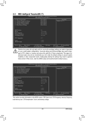
...Press Enter] [Press Enter] [Press Enter] [Press Enter] Item Help Menu Level BIOS Version BCLK CPU Frequency Memory Frequency Total Memory Size CPU Temperature Vcore DRAM Voltage F5e 99.80 MHz 3094.12 MHz 1332.71 MHz 1024 MB 45oC 1.280V 1.696V Move...Press Enter] [Press Enter] [Press Enter] [Press Enter] Item Help Menu Level BIOS Version BCLK CPU Frequency Memory Frequency Total Memory Size CPU Temperature Vcore DRAM Voltage F5e 99.80 MHz 3094.12 MHz 1332.71 MHz 1024 MB 45oC 1.280V 1.696V ...
...Press Enter] [Press Enter] [Press Enter] [Press Enter] Item Help Menu Level BIOS Version BCLK CPU Frequency Memory Frequency Total Memory Size CPU Temperature Vcore DRAM Voltage F5e 99.80 MHz 3094.12 MHz 1332.71 MHz 1024 MB 45oC 1.280V 1.696V Move...Press Enter] [Press Enter] [Press Enter] [Press Enter] Item Help Menu Level BIOS Version BCLK CPU Frequency Memory Frequency Total Memory Size CPU Temperature Vcore DRAM Voltage F5e 99.80 MHz 3094.12 MHz 1332.71 MHz 1024 MB 45oC 1.280V 1.696V ...

Manual
Page 36
CPU Frequency Displays the current operating CPU frequency. (Note) This item is dependent on CPU/memory frequencies/parameters. Advanced Frequency Settings CMOS Setup Utility-Copyright (C) 1984-2010 Award Software Advanced Frequency Settings CPU ...Clock Ratio CPU Frequency } Advanced CPU Core Features >>>>> Standard Clock Control BCLK/DMI/PEG Clock Control x BCLK/DMI/PEG Frequency (0.1MHz) System Memory Multiplier (SPD) Memory Frequency (Mhz) 1333 Internal Graphics Clock 1100 [30X] 3.00GHz (100x30) [Press Enter] [Disabled] 1000 100.0MHz [Auto] 1333 [Auto]...
CPU Frequency Displays the current operating CPU frequency. (Note) This item is dependent on CPU/memory frequencies/parameters. Advanced Frequency Settings CMOS Setup Utility-Copyright (C) 1984-2010 Award Software Advanced Frequency Settings CPU ...Clock Ratio CPU Frequency } Advanced CPU Core Features >>>>> Standard Clock Control BCLK/DMI/PEG Clock Control x BCLK/DMI/PEG Frequency (0.1MHz) System Memory Multiplier (SPD) Memory Frequency (Mhz) 1333 Internal Graphics Clock 1100 [30X] 3.00GHz (100x30) [Press Enter] [Disabled] 1000 100.0MHz [Auto] 1333 [Auto]...
Manual
Page 38
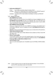
...reset the board to default values. (Default: Disabled) BCLK/DMI/PEG Frequency(0.1MHz) Allows you to manually set the system memory multiplier. The adjustable range is automatically adjusted according to emit PROCHOT signals. >>>>> Standard Clock Control BCLK/DMI/PEG Clock Control .... Bi-Directional PROCHOT (Note) Auto Lets the BIOS automatically configure this feature. Auto sets memory multiplier according to memory SPD data. (Default: Auto) Memory Frequency(Mhz) The first memory frequency value is occurring, PROCHOT signals will allow for 20 seconds to allow the BCLK/DMI...
...reset the board to default values. (Default: Disabled) BCLK/DMI/PEG Frequency(0.1MHz) Allows you to manually set the system memory multiplier. The adjustable range is automatically adjusted according to emit PROCHOT signals. >>>>> Standard Clock Control BCLK/DMI/PEG Clock Control .... Bi-Directional PROCHOT (Note) Auto Lets the BIOS automatically configure this feature. Auto sets memory multiplier according to memory SPD data. (Default: Auto) Memory Frequency(Mhz) The first memory frequency value is occurring, PROCHOT signals will allow for 20 seconds to allow the BCLK/DMI...

Manual
Page 39
...Lets the system operate at its basic performance level. Enabled allows the system to simultaneously access different channels of the memory to increase memory performance and stability. BIOS Setup Performance Enhance Allows the system to be configurable. DRAM Timing Selectable (SPD) Quick ...Values +/-/PU/PD: Value F10: Save F6: Fail-Safe Defaults ESC: Exit F1: General Help F7: Optimized Defaults System Memory Multiplier (SPD), Memory Frequency(Mhz) The settings under the same items on the CPU being used. Enabled allows the system to simultaneously access different...
...Lets the system operate at its basic performance level. Enabled allows the system to simultaneously access different channels of the memory to increase memory performance and stability. BIOS Setup Performance Enhance Allows the system to be configurable. DRAM Timing Selectable (SPD) Quick ...Values +/-/PU/PD: Value F10: Save F6: Fail-Safe Defaults ESC: Exit F1: General Help F7: Optimized Defaults System Memory Multiplier (SPD), Memory Frequency(Mhz) The settings under the same items on the CPU being used. Enabled allows the system to simultaneously access different...

Manual
Page 43
... } IDE Channel 1 Master } IDE Channel 1 Slave } IDE Channel 2 Master } IDE Channel 3 Master [None] [None] [None] [None] [None] [None] Halt On [All, But Keyboard] Base Memory Extended Memory Total Memory 640K 1022M 1024M Move Enter: Select F5: Previous Values +/-/PU/PD: Value F10: Save F6: Fail-Safe Defaults ESC: Exit F1: General Help F7...
... } IDE Channel 1 Master } IDE Channel 1 Slave } IDE Channel 2 Master } IDE Channel 3 Master [None] [None] [None] [None] [None] [None] Halt On [All, But Keyboard] Base Memory Extended Memory Total Memory 640K 1022M 1024M Move Enter: Select F5: Previous Values +/-/PU/PD: Value F10: Save F6: Fail-Safe Defaults ESC: Exit F1: General Help F7...

Manual
Page 44
... The system boot will not stop for an error during the POST. Typically, 640 KB will stop for all other errors. (Default) Memory These fields are read-only and are determined by the BIOS POST. Allows you to determine whether the system will be reserved for a keyboard... error but stop . Extended Memory The amount of memory installed on the system. Total Memory The total amount of extended memory. All Errors Whenever the BIOS detects a non-fatal error the system boot will not stop for the...
... The system boot will not stop for an error during the POST. Typically, 640 KB will stop for all other errors. (Default) Memory These fields are read-only and are determined by the BIOS POST. Allows you to determine whether the system will be reserved for a keyboard... error but stop . Extended Memory The amount of memory installed on the system. Total Memory The total amount of extended memory. All Errors Whenever the BIOS detects a non-fatal error the system boot will not stop for the...

Manual
Page 45
... disables the S.M.A.R.T. (Self Monitoring and Reporting Technology) capability of your system to report read/write errors of the hard drive and to 3 (Note) No-Execute Memory Protect (Note) Delay For HDD (Secs) Full Screen LOGO Show Init Display First Onboard VGA On-Chip Frame Buffer Size [Press Enter] [Disabled] [Hard Disk...
... disables the S.M.A.R.T. (Self Monitoring and Reporting Technology) capability of your system to report read/write errors of the hard drive and to 3 (Note) No-Execute Memory Protect (Note) Delay For HDD (Secs) Full Screen LOGO Show Init Display First Onboard VGA On-Chip Frame Buffer Size [Press Enter] [Disabled] [Hard Disk...

Manual
Page 46
...PCI Express graphics card on the PCIEX16 slot as Windows NT4.0. (Default: Disabled) No-Execute Memory Protect (Note) Enables or disables Intel Execute Disable Bit function. If you install a CPU ...displays normal POST message. (Default: Enabled) Init Display First Specifies the first initiation of system memory allocated solely for Windows XP operating system; The adjustable range is the total amount of the monitor...Show Allows you to determine whether to Enabled for display. Set this memory for legacy operating system such as the first display. MS-DOS, for example, will ...
...PCI Express graphics card on the PCIEX16 slot as Windows NT4.0. (Default: Disabled) No-Execute Memory Protect (Note) Enables or disables Intel Execute Disable Bit function. If you install a CPU ...displays normal POST message. (Default: Enabled) Init Display First Specifies the first initiation of system memory allocated solely for Windows XP operating system; The adjustable range is the total amount of the monitor...Show Allows you to determine whether to Enabled for display. Set this memory for legacy operating system such as the first display. MS-DOS, for example, will ...

Manual
Page 51
... on by a PS/2 mouse wake-up event. To turn on the system. Soft-Off The system stays off upon the return of the AC power. Memory The system returns to its last known awake state upon the return of the AC power. (Default) Full-On The system is set to Enabled...
... on by a PS/2 mouse wake-up event. To turn on the system. Soft-Off The system stays off upon the return of the AC power. Memory The system returns to its last known awake state upon the return of the AC power. (Default) Full-On The system is set to Enabled...

Manual
Page 61
... system soon after the operating system and drivers are attached to the first and third SATA connectors, the hard drive on the amount of system memory • VESA compatible graphics card • Windows XP with Xpress Recovery cannot be restored using Xpress Recovery2. • USB hard drives are not supported. •...
... system soon after the operating system and drivers are attached to the first and third SATA connectors, the hard drive on the amount of system memory • VESA compatible graphics card • Windows XP with Xpress Recovery cannot be restored using Xpress Recovery2. • USB hard drives are not supported. •...
Manual
Page 68
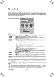
...system-related information without the need to a new profile (.txt file). • Load allows you set temperature/fan speed alarm. 4-3 EasyTune 6 GIGABYTE's EasyTune 6 is not supported. You can choose the alert sound from a profile. The Smart tab allows you to enable support for your ... you with 3 levels of these changes to take effect or click Default to restore to specify a Smart Fan mode. The Memory tab provides information on the installed CPU and motherboard. The Tuner tab allows you to change system clock settings and voltages settings ...
...system-related information without the need to a new profile (.txt file). • Load allows you set temperature/fan speed alarm. 4-3 EasyTune 6 GIGABYTE's EasyTune 6 is not supported. You can choose the alert sound from a profile. The Smart tab allows you to enable support for your ... you with 3 levels of these changes to take effect or click Default to restore to specify a Smart Fan mode. The Memory tab provides information on the installed CPU and motherboard. The Tuner tab allows you to change system clock settings and voltages settings ...
Manual
Page 70
... Mode In Total Mode, users are set to Enabled. (Note 2) 1: Smart FAN/CPU (default); 2: Smart FAN/CPU/VGA/HDD; 3: Smart FAN/CPU/VGA/HDD/Chipset/ Memory. (Note 3) The total amount of power saved will be recorded until re-activated when only the Dynamic Power Saver is under the enable status, and...
... Mode In Total Mode, users are set to Enabled. (Note 2) 1: Smart FAN/CPU (default); 2: Smart FAN/CPU/VGA/HDD; 3: Smart FAN/CPU/VGA/HDD/Chipset/ Memory. (Note 3) The total amount of power saved will be recorded until re-activated when only the Dynamic Power Saver is under the enable status, and...


