Manual
Page 2
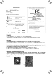
...like this manual may be made by any form or by GIGABYTE without GIGABYTE's prior written permission. „„ In order to their respective owners. Disclaimer Information in this : "REV: X.X." Motherboard GA-H61M-S2PH Motherboard GA-H61M-S2PH Mar. 29, 2013 Mar. 29, 2013 Copyright ©... 2013 GIGA-BYTE TECHNOLOGY CO., LTD. No part of GIGABYTE. Example: For example, "REV: 1.0" means the revision of the ...
...like this manual may be made by any form or by GIGABYTE without GIGABYTE's prior written permission. „„ In order to their respective owners. Disclaimer Information in this : "REV: X.X." Motherboard GA-H61M-S2PH Motherboard GA-H61M-S2PH Mar. 29, 2013 Mar. 29, 2013 Copyright ©... 2013 GIGA-BYTE TECHNOLOGY CO., LTD. No part of GIGABYTE. Example: For example, "REV: 1.0" means the revision of the ...
Manual
Page 3
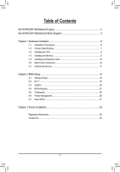
Table of Contents GA-H61M-S2PH Motherboard Layout 4 GA-H61M-S2PH Motherboard Block Diagram 5 Chapter 1 Hardware Installation 6 1-1 Installation Precautions 6 1-2 Product Specifications 7 1-3 Installing the CPU 9 1-4 Installing the Memory 9 1-5 Installing an Expansion Card 10 1-6 Back Panel Connectors 10 1-7 Internal Connectors 11 Chapter 2 BIOS Setup 15 2-1 Startup Screen 16 2-2 M.I.T...16 2-3 System...20 2-4 BIOS Features 21 2-5 Peripherals...24 2-6 Power Management 26 2-7 Save & Exit...27 Chapter 3 Drivers Installation 28 Regulatory Statements 29 Contact Us...32 - 3 -
Table of Contents GA-H61M-S2PH Motherboard Layout 4 GA-H61M-S2PH Motherboard Block Diagram 5 Chapter 1 Hardware Installation 6 1-1 Installation Precautions 6 1-2 Product Specifications 7 1-3 Installing the CPU 9 1-4 Installing the Memory 9 1-5 Installing an Expansion Card 10 1-6 Back Panel Connectors 10 1-7 Internal Connectors 11 Chapter 2 BIOS Setup 15 2-1 Startup Screen 16 2-2 M.I.T...16 2-3 System...20 2-4 BIOS Features 21 2-5 Peripherals...24 2-6 Power Management 26 2-7 Save & Exit...27 Chapter 3 Drivers Installation 28 Regulatory Statements 29 Contact Us...32 - 3 -
Manual
Page 4
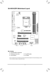
... iTE Super I/O PCIEX1 PCI1 PCIe to PCI Bridge Intel® H61 SATA2 3 2 1 0 CODEC PCI2 F_AUDIO COMB F_USB2 F_USB1 SPDIF_O SYS_FAN CLR_CMOS F_PANEL Box Contents 55 GA-H61M-S2PH motherboard 55 Motherboard driver disk 55 User's Manual 55 Two SATA cables 55 I/O Shield The box contents above are subject to change without notice. - 4 - The...
... iTE Super I/O PCIEX1 PCI1 PCIe to PCI Bridge Intel® H61 SATA2 3 2 1 0 CODEC PCI2 F_AUDIO COMB F_USB2 F_USB1 SPDIF_O SYS_FAN CLR_CMOS F_PANEL Box Contents 55 GA-H61M-S2PH motherboard 55 Motherboard driver disk 55 User's Manual 55 Two SATA cables 55 I/O Shield The box contents above are subject to change without notice. - 4 - The...
Manual
Page 5
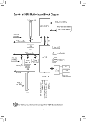
GA-H61M-S2PH Motherboard Block Diagram 1 PCI Express x16 LGA1155 CPU PCIe CLK (100 MHz) x16 PCI Express Bus CPU CLK+/- (100 MHz) DDR3 1333/1066/800 MHz ...
GA-H61M-S2PH Motherboard Block Diagram 1 PCI Express x16 LGA1155 CPU PCIe CLK (100 MHz) x16 PCI Express Bus CPU CLK+/- (100 MHz) DDR3 1333/1066/800 MHz ...
Manual
Page 13
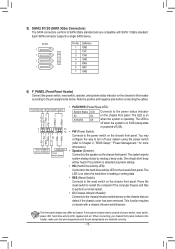
... and the pin assignments are compatible with a chassis intrusion switch/sensor. 1 23 SMB_CPT The front panel design may HD+ HD- CLR_CMOS CI DIS_ME GP15_CPT (GA-IVB) S0 On on the chassis front panel. Each SATA connector supports a single SATA device. The LED is off when the system is detected at... (S5). DIP 1 23 1 M_SATA •• RES (Reset Switch): DIP 1 23 1 Connects to the chassis intrusion switch/sensor on the chassis front panel. BIOS_PH (GA-IVB) •• CI (Chassis Intrusion Header): Connects to the reset switch on the chassis front panel.
... and the pin assignments are compatible with a chassis intrusion switch/sensor. 1 23 SMB_CPT The front panel design may HD+ HD- CLR_CMOS CI DIS_ME GP15_CPT (GA-IVB) S0 On on the chassis front panel. Each SATA connector supports a single SATA device. The LED is off when the system is detected at... (S5). DIP 1 23 1 M_SATA •• RES (Reset Switch): DIP 1 23 1 Connects to the chassis intrusion switch/sensor on the chassis front panel. BIOS_PH (GA-IVB) •• CI (Chassis Intrusion Header): Connects to the reset switch on the chassis front panel.


