Manual
Page 5
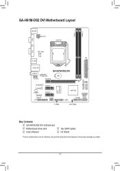
GA-H61M-DS2 DVI Motherboard Layout VGA KB_MS ATX_12V LGA1155 DDR3_1 DDR3_2 DVI CPU_FAN ATX R_USB USB_LAN AUDIO F_AUDIO GA-H61M-DS2 DVI Realtek GbE LAN BAT PCIEX16 M_BIOS B_BIOS CODEC SYS_FAN LPT PCIEX1_1 PCIEX1_2 COMA F_USB2 iTE Super I/O Intel® H61 F_USB1 F_PANEL CLR_CMOS SATA2 32 SATA2 1 0 Box Contents 55 GA-H61M-DS2 DVI motherboard 55 Motherboard driver disk 55 User's Manual 55 Two SATA cables 55 I/O Shield The box contents above are for reference only and the actual items shall depend on the product package you obtain. - 5 -
GA-H61M-DS2 DVI Motherboard Layout VGA KB_MS ATX_12V LGA1155 DDR3_1 DDR3_2 DVI CPU_FAN ATX R_USB USB_LAN AUDIO F_AUDIO GA-H61M-DS2 DVI Realtek GbE LAN BAT PCIEX16 M_BIOS B_BIOS CODEC SYS_FAN LPT PCIEX1_1 PCIEX1_2 COMA F_USB2 iTE Super I/O Intel® H61 F_USB1 F_PANEL CLR_CMOS SATA2 32 SATA2 1 0 Box Contents 55 GA-H61M-DS2 DVI motherboard 55 Motherboard driver disk 55 User's Manual 55 Two SATA cables 55 I/O Shield The box contents above are for reference only and the actual items shall depend on the product package you obtain. - 5 -
Manual
Page 7
... steps or have it on top of an antistatic pad or within an electrostatic shielding container. •• Before unplugging the power supply cable from the motherboard, make sure the power supply has been turned off. •• Before turning on the power, make sure the ...sure the power supply voltage has been set according to the local voltage standard. •• Before using the product, please verify that all cables and power connectors of your hands dry and first touch a metal object to eliminate static electricity. •• Prior to installing the motherboard,...
... steps or have it on top of an antistatic pad or within an electrostatic shielding container. •• Before unplugging the power supply cable from the motherboard, make sure the power supply has been turned off. •• Before turning on the power, make sure the ...sure the power supply voltage has been set according to the local voltage standard. •• Before using the product, please verify that all cables and power connectors of your hands dry and first touch a metal object to eliminate static electricity. •• Prior to installing the motherboard,...
Manual
Page 12
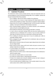
... (Note) The DVI-D port conforms to the DVI-D specification and supports a maximum resolution of the LAN port LEDs. Line Out Jack (Green) The default line out jack. Do not rock it straight out from the motherboard. •• When removing the cable, pull it side to side to connect front speakers in devices...
... (Note) The DVI-D port conforms to the DVI-D specification and supports a maximum resolution of the LAN port LEDs. Line Out Jack (Green) The default line out jack. Do not rock it straight out from the motherboard. •• When removing the cable, pull it side to side to connect front speakers in devices...
Manual
Page 13
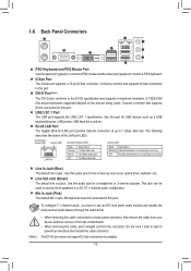
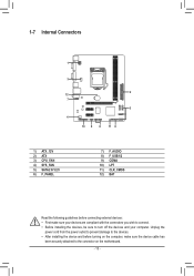
... with the connectors you wish to connect. •• Before installing the devices, be sure to the connector on the computer, make sure the device cable has been securely attached to turn off the devices and your computer. 1-7 Internal Connectors 1 3 2 12 7 5 4 10 9 8 11 6 1) ATX_12V 2) ATX 3) CPU_FAN 4) SYS_FAN 5) SATA2 0/1/2/3 6) F_PANEL 7) F_AUDIO 8) F_USB1...
... with the connectors you wish to connect. •• Before installing the devices, be sure to the connector on the computer, make sure the device cable has been securely attached to turn off the devices and your computer. 1-7 Internal Connectors 1 3 2 12 7 5 4 10 9 8 11 6 1) ATX_12V 2) ATX 3) CPU_FAN 4) SYS_FAN 5) SATA2 0/1/2/3 6) F_PANEL 7) F_AUDIO 8) F_USB1...
Manual
Page 14
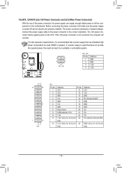
The 12V power connector mainly supplies power to the power connector in the correct orientation. Connect the power supply cable to the CPU. The power connector possesses a foolproof design. If a power supply is recommended that a power supply that can withstand high power consumption be used ...
The 12V power connector mainly supplies power to the power connector in the correct orientation. Connect the power supply cable to the CPU. The power connector possesses a foolproof design. If a power supply is recommended that a power supply that can withstand high power consumption be used ...
Manual
Page 15
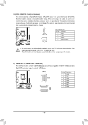
...32 1 7 - 15 - Definition 1 GND 2 +12V 3 Sense 4 Speed Control DEBUG PORT DEBUG PORT •• Be sure to connect fan cables to the fan headers to SATA 3Gb/s standard and are not configuration jumper blocks. 3/4) CPU_FAN/SYS_FAN (Fan Headers) The motherboard has a 4-pin CPU ... foolproof insertion design. Each SATA connector supports a single SATA device. Do not place a jumper cap on the headers. When connecting a fan cable, be installed inside the chassis. 1 CPU_FAN 1 SYS_FAN CPU_FAN/SYS_FAN: Pin No. Overheating may hang. •• These fan headers are ...
...32 1 7 - 15 - Definition 1 GND 2 +12V 3 Sense 4 Speed Control DEBUG PORT DEBUG PORT •• Be sure to connect fan cables to the fan headers to SATA 3Gb/s standard and are not configuration jumper blocks. 3/4) CPU_FAN/SYS_FAN (Fan Headers) The motherboard has a 4-pin CPU ... foolproof insertion design. Each SATA connector supports a single SATA device. Do not place a jumper cap on the headers. When connecting a fan cable, be installed inside the chassis. 1 CPU_FAN 1 SYS_FAN CPU_FAN/SYS_FAN: Pin No. Overheating may hang. •• These fan headers are ...
Manual
Page 16
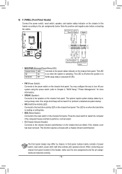
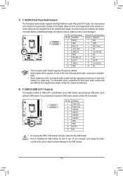
...wire assignments and the pin assignments are matched correctly. - 16 - Note the positive and negative pins before connecting the cables. RESRES+ CICI+ PWR+ PWR- DIP 1 23 1 DIP 1 23 1 M_SATA DIP 1 23 1 •... activity LED, speaker and etc. F_AUDIO(H) F_PANEL(NH) 2 1 20 F_PANEL 19 (H61M-D2) HD+ HD- The LED is off (S5). suing a beep code. ement points(G1.Sniper 3) BIOS...detected at system stSaMrBtu_pC.PT PCIe power••conHnDect(oHr (aSrAdTAD)(rXi5v8eAA-OcCt)ivity LED): (GA-IVB) Connects to the pin assignments below. One sing1 l2e3 short beep will be heard if...
...wire assignments and the pin assignments are matched correctly. - 16 - Note the positive and negative pins before connecting the cables. RESRES+ CICI+ PWR+ PWR- DIP 1 23 1 DIP 1 23 1 M_SATA DIP 1 23 1 •... activity LED, speaker and etc. F_AUDIO(H) F_PANEL(NH) 2 1 20 F_PANEL 19 (H61M-D2) HD+ HD- The LED is off (S5). suing a beep code. ement points(G1.Sniper 3) BIOS...detected at system stSaMrBtu_pC.PT PCIe power••conHnDect(oHr (aSrAdTAD)(rXi5v8eAA-OcCt)ivity LED): (GA-IVB) Connects to the pin assignments below. One sing1 l2e3 short beep will be heard if...
Manual
Page 17
...) 3 USB DX- 4 USB DY- 5 USB DX+ 6 USB DY+ 7 GND 8 GND 9 No Pin 10 NC •• Do not plug the IEEE 1394 bracket (2x5-pin) cable into the USB header. •• Prior to installing the USB bracket, be present on each wire instead of the motherboard header. For information about...
...) 3 USB DX- 4 USB DY- 5 USB DX+ 6 USB DY+ 7 GND 8 GND 9 No Pin 10 NC •• Do not plug the IEEE 1394 bracket (2x5-pin) cable into the USB header. •• Prior to installing the USB bracket, be present on each wire instead of the motherboard header. For information about...
Manual
Page 18
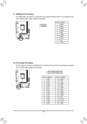
... 23 24 25 26 Definition GND PD6 GND PD7 GND ACKGND BUSY GND PE No Pin SLCT GND - 18 - For purchasing the optional COM port cable, please contact the local dealer. 9 1 10 2 DEBUG PORT Pin No. 1 2 3 4 5 6 7 8 9 10 Definition NDCDNSIN NSOUT NDTRGND NDSRNRTSNCTSNRINo Pin 10) LPT (Parallel Port Header) ...The LPT header can provide one parallel port via an optional COM port cable. 9) COMA (Serial Port Header) The COM header can provide one serial port via an optional LPT port...
... 23 24 25 26 Definition GND PD6 GND PD7 GND ACKGND BUSY GND PE No Pin SLCT GND - 18 - For purchasing the optional COM port cable, please contact the local dealer. 9 1 10 2 DEBUG PORT Pin No. 1 2 3 4 5 6 7 8 9 10 Definition NDCDNSIN NSOUT NDTRGND NDSRNRTSNCTSNRINo Pin 10) LPT (Parallel Port Header) ...The LPT header can provide one parallel port via an optional COM port cable. 9) COMA (Serial Port Header) The COM header can provide one serial port via an optional LPT port...


