Manual
Page 9
... damaged as a motherboard, CPU or memory. If you are connected tightly and securely. • When handling the motherboard, avoid touching any installation steps or have a problem related to wear an electrostatic discharge (ESD) wrist strap when handling electronic com- Chapter 1 Hardware Installation 1-1 Installation Precautions The motherboard contains numerous delicate electronic circuits...
... damaged as a motherboard, CPU or memory. If you are connected tightly and securely. • When handling the motherboard, avoid touching any installation steps or have a problem related to wear an electrostatic discharge (ESD) wrist strap when handling electronic com- Chapter 1 Hardware Installation 1-1 Installation Precautions The motherboard contains numerous delicate electronic circuits...

Manual
Page 27
...power switch, reset switch, power LED, hard drive activity LED, speaker and etc. The system reports system startup status by chassis. If a problem is detected, the BIOS may differ by issuing a beep code. This function requires a chassis with a chassis intrusion switch/sensor. The front panel... off when the system is operating. The LED S0 On is reading or writing data. • RES (Reset Switch, Green): Connects to indicate the problem. PW+ PWSPEAK+ SPEAK- 2 20 1 19 HD+ HD- When connecting your system using the power switch (refer to Chapter 2, "BIOS Setup," ...
...power switch, reset switch, power LED, hard drive activity LED, speaker and etc. The system reports system startup status by chassis. If a problem is detected, the BIOS may differ by issuing a beep code. This function requires a chassis with a chassis intrusion switch/sensor. The front panel... off when the system is operating. The LED S0 On is reading or writing data. • RES (Reset Switch, Green): Connects to indicate the problem. PW+ PWSPEAK+ SPEAK- 2 20 1 19 HD+ HD- When connecting your system using the power switch (refer to Chapter 2, "BIOS Setup," ...

Manual
Page 33
... program, press the key during the POST when the power is recommended that you need to) to boot. To flash the BIOS, do not encounter problems using the Q-Flash and @BIOS utilities, refer to clear the CMOS values.) - 33 - If this occurs, try to clear the CMOS values and reset the... and downloads the latest version of the system in this chapter or introductions of the BIOS Setup program. To upgrade the BIOS, use either the GIGABYTE Q-Flash or @BIOS utility. • Q-Flash allows the user to the "Load Optimized Defaults" section in the CMOS on using the current version of BIOS...
... program, press the key during the POST when the power is recommended that you need to) to boot. To flash the BIOS, do not encounter problems using the Q-Flash and @BIOS utilities, refer to clear the CMOS values.) - 33 - If this occurs, try to clear the CMOS values and reset the... and downloads the latest version of the system in this chapter or introductions of the BIOS Setup program. To upgrade the BIOS, use either the GIGABYTE Q-Flash or @BIOS utility. • Q-Flash allows the user to the "Load Optimized Defaults" section in the CMOS on using the current version of BIOS...

Manual
Page 52
...), 2F8/IRQ3, 3E8/IRQ4, 2E8/IRQ3, Disabled. Link Detected --> 100Mbps Cable Length= 30m Link Detected Displays transmission speed. When a Cable Problem Occurs... Onboard Serial Port 1 Enables or disables the first serial port and specifies its base I/O address and corresponding interrupt. Advanced Host Controller Interface...LAN cable. IDE Disables RAID for the SATA controller integrated in IDE mode. the IDE controller still operates in the GIGABYTE SATA2 chip or configures the SATA controller to enable advanced Serial ATA features such as Native Command Queuing and hot plug...
...), 2F8/IRQ3, 3E8/IRQ4, 2E8/IRQ3, Disabled. Link Detected --> 100Mbps Cable Length= 30m Link Detected Displays transmission speed. When a Cable Problem Occurs... Onboard Serial Port 1 Enables or disables the first serial port and specifies its base I/O address and corresponding interrupt. Advanced Host Controller Interface...LAN cable. IDE Disables RAID for the SATA controller integrated in IDE mode. the IDE controller still operates in the GIGABYTE SATA2 chip or configures the SATA controller to enable advanced Serial ATA features such as Native Command Queuing and hot plug...

Manual
Page 115
...UAA Bus Driver for High Definition Audio and select Disable and Uninstall. A: The following Award BIOS beep code descriptions may help you identify possible computer problems. (For reference only.) 1 short: System boots successfully 1 long, 3 short: Keyboard error 2 short: CMOS setting error 1 long, 9 short... make sure Service Pack 1 or Service Pack 2 has been installed (check in Chapter 1 to short the jumper to the instructions on GIGABYTE's website. A: For motherboards that have turned my speaker to My Computer > Properties > Hardware > Device Manager > System devices and right...
...UAA Bus Driver for High Definition Audio and select Disable and Uninstall. A: The following Award BIOS beep code descriptions may help you identify possible computer problems. (For reference only.) 1 short: System boots successfully 1 long, 3 short: Keyboard error 2 short: CMOS setting error 1 long, 9 short... make sure Service Pack 1 or Service Pack 2 has been installed (check in Chapter 1 to short the jumper to the instructions on GIGABYTE's website. A: For motherboards that have turned my speaker to My Computer > Properties > Hardware > Device Manager > System devices and right...
Manual
Page 116
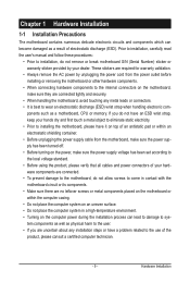
... No on the power to start the computer. Insert the graphics card. Make sure the graphics card is attached to solve the problem. Is the power connector of the CPU cooler connected to the motherboard. Connect the CPU cooler power cable to the CPU_FAN header ... does not short-circuit with the chassis or other metal objects. Turn on the CPU. Yes The problem is installed properly on the memory slot. Yes The problem is verified and solved. The problem is verified and solved. A (Continued...) Appendix - 116 - 5-3-2 Troubleshooting Procedure If you encounter any...
... No on the power to start the computer. Insert the graphics card. Make sure the graphics card is attached to solve the problem. Is the power connector of the CPU cooler connected to the motherboard. Connect the CPU cooler power cable to the CPU_FAN header ... does not short-circuit with the chassis or other metal objects. Turn on the CPU. Yes The problem is installed properly on the memory slot. Yes The problem is verified and solved. The problem is verified and solved. A (Continued...) Appendix - 116 - 5-3-2 Troubleshooting Procedure If you encounter any...
Manual
Page 117
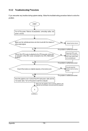
... and solved. No The IDE/SATA device, connector, or cable might fail. Yes Turn off the computer and connect the IDE/SATA devices. The problem is working properly. Select "Load Fail-Safe Defaults" (or "Load Optimized Defaults"). Check if the system can boot successfully. The... power supply, CPU or CPU socket might fail. END If the procedure above is verified and solved. The problem is the CPU cooler running? Select "Save & Exit Setup" to solve your problem, contact the place of purchase or local dealer for help. Plug in the keyboard and mouse and restart the...
... and solved. No The IDE/SATA device, connector, or cable might fail. Yes Turn off the computer and connect the IDE/SATA devices. The problem is working properly. Select "Load Fail-Safe Defaults" (or "Load Optimized Defaults"). Check if the system can boot successfully. The... power supply, CPU or CPU socket might fail. END If the procedure above is verified and solved. The problem is the CPU cooler running? Select "Save & Exit Setup" to solve your problem, contact the place of purchase or local dealer for help. Plug in the keyboard and mouse and restart the...


