Manual
Page 3
.... Example: Disclaimer Information in the use GIGABYTE's unique features, read or download the information on/from the Support&Downloads\Motherboard\Technology Guide page on your motherboard revision before updating motherboard BIOS, drivers, or when looking for technical information.... Documentation Classifications In order to assist in this product, GIGABYTE provides the following types of GIGABYTE. Copyright © 2010 GIGA-BYTE TECHNOLOGY CO.,...
.... Example: Disclaimer Information in the use GIGABYTE's unique features, read or download the information on/from the Support&Downloads\Motherboard\Technology Guide page on your motherboard revision before updating motherboard BIOS, drivers, or when looking for technical information.... Documentation Classifications In order to assist in this product, GIGABYTE provides the following types of GIGABYTE. Copyright © 2010 GIGA-BYTE TECHNOLOGY CO.,...
Manual
Page 4
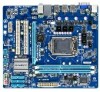
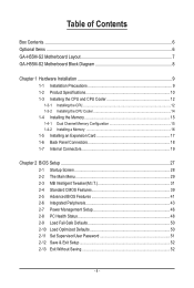
Table of Contents Box Contents...6 Optional Items...6 GA-H55M-S2 Motherboard Layout 7 GA-H55M-S2 Motherboard Block Diagram 8 Chapter 1 Hardware Installation 9 1-1 Installation Precautions 9 1-2 Product Specifications 10 1-3 Installing the CPU and CPU ...Installing an Expansion Card 17 1-6 Back Panel Connectors 18 1-7 Internal Connectors 19 Chapter 2 BIOS Setup 27 2-1 Startup Screen 28 2-2 The Main Menu 29 2-3 MB Intelligent Tweaker(M.I.T 31 2-4 Standard CMOS Features 39 2-5 Advanced BIOS Features 41 2-6 Integrated Peripherals 43 2-7 Power Management Setup 46 2-8 PC Health Status ...
Table of Contents Box Contents...6 Optional Items...6 GA-H55M-S2 Motherboard Layout 7 GA-H55M-S2 Motherboard Block Diagram 8 Chapter 1 Hardware Installation 9 1-1 Installation Precautions 9 1-2 Product Specifications 10 1-3 Installing the CPU and CPU ...Installing an Expansion Card 17 1-6 Back Panel Connectors 18 1-7 Internal Connectors 19 Chapter 2 BIOS Setup 27 2-1 Startup Screen 28 2-2 The Main Menu 29 2-3 MB Intelligent Tweaker(M.I.T 31 2-4 Standard CMOS Features 39 2-5 Advanced BIOS Features 41 2-6 Integrated Peripherals 43 2-7 Power Management Setup 46 2-8 PC Health Status ...
Manual
Page 5
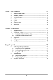
... 54 3-4 Contact...55 3-5 System...55 3-6 Download Center 56 3-7 New Utilities...56 Chapter 4 Unique Features 57 4-1 Xpress Recovery2 57 4-2 BIOS Update Utilities 60 4-2-1 Updating the BIOS with the Q-Flash Utility 60 4-2-2 Updating the BIOS with the @BIOS Utility 63 4-3 EasyTune 6...64 4-4 Q-Share...65 4-5 Auto Green...66 Chapter 5 Appendix...67 5-1 Configuring Audio Input and Output 67...
... 54 3-4 Contact...55 3-5 System...55 3-6 Download Center 56 3-7 New Utilities...56 Chapter 4 Unique Features 57 4-1 Xpress Recovery2 57 4-2 BIOS Update Utilities 60 4-2-1 Updating the BIOS with the Q-Flash Utility 60 4-2-2 Updating the BIOS with the @BIOS Utility 63 4-3 EasyTune 6...64 4-4 Q-Share...65 4-5 Auto Green...66 Chapter 5 Appendix...67 5-1 Configuring Audio Input and Output 67...
Manual
Page 8
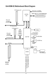
GA-H55M-S2 Motherboard Block Diagram 1 PCI Express x16 LGA1156 CPU CPU CLK+/- (133 MHz) DDR3 1666 (O.C.)/1333/1066/800 MHz Dual Channel Memory PCIe CLK (100 MHz) x16 PCI Express Bus 1 PCI Express x1 LAN PCIe CLK (100 MHz) PCI Express Bus x1 RJ45 Realtek RTL8111E x1 PCI Bus FDI Interface DMI Interface Intel® H55 D-Sub Dual BIOS 6 SATA 3Gb/s 12 USB Ports CODEC LPC Bus iTE IT8720 PS/2 KB/Mouse 2 PCI PCI CLK (33 MHz) MIC (Center/Subwoofer Speakcer Out ) Line Out (Front Speakcer Out ) Line In (Rear Speakcer Out ) - 8 -
GA-H55M-S2 Motherboard Block Diagram 1 PCI Express x16 LGA1156 CPU CPU CLK+/- (133 MHz) DDR3 1666 (O.C.)/1333/1066/800 MHz Dual Channel Memory PCIe CLK (100 MHz) x16 PCI Express Bus 1 PCI Express x1 LAN PCIe CLK (100 MHz) PCI Express Bus x1 RJ45 Realtek RTL8111E x1 PCI Bus FDI Interface DMI Interface Intel® H55 D-Sub Dual BIOS 6 SATA 3Gb/s 12 USB Ports CODEC LPC Bus iTE IT8720 PS/2 KB/Mouse 2 PCI PCI CLK (33 MHz) MIC (Center/Subwoofer Speakcer Out ) Line Out (Front Speakcer Out ) Line In (Rear Speakcer Out ) - 8 -
Manual
Page 11
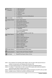
Hardware Installation Back Panel w Connectors w w w w w I/O Controller w Hardware Monitor w w w w w w BIOS w w w w Unique Features w w w w w w w w w w Bundled Software w 1 x PS/2 keyboard port 1 x PS/2 mouse port 1 x D-Sub ...8 Mbit flash Use of licensed AWARD BIOS Support for DualBIOS™ PnP 1.0a, DMI 2.0, SM BIOS 2.4, ACPI 1.0b Support for @BIOS Support for Q-Flash Support for Xpress BIOS Rescue Support for Download Center Support for...
Hardware Installation Back Panel w Connectors w w w w w I/O Controller w Hardware Monitor w w w w w w BIOS w w w w Unique Features w w w w w w w w w w Bundled Software w 1 x PS/2 keyboard port 1 x PS/2 mouse port 1 x D-Sub ...8 Mbit flash Use of licensed AWARD BIOS Support for DualBIOS™ PnP 1.0a, DMI 2.0, SM BIOS 2.4, ACPI 1.0b Support for @BIOS Support for Q-Flash Support for Xpress BIOS Rescue Support for Download Center Support for...
Manual
Page 15
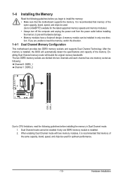
... power cord from the power outlet before installing the memory to insert the memory, switch the direction. Hardware Installation If you begin to GIGABYTE's website for optimum performance. - 15 - Dual Channel mode cannot be used . (Go to install the memory: • Make sure.... 1-4 Installing the Memory 1-4-1 Read the following guidelines before installing the memory in only one DDR3 memory module is installed, the BIOS will double the original memory bandwidth. Enabling Dual Channel memory mode will automatically detect the specifications and capacity of the same capacity,...
... power cord from the power outlet before installing the memory to insert the memory, switch the direction. Hardware Installation If you begin to GIGABYTE's website for optimum performance. - 15 - Dual Channel mode cannot be used . (Go to install the memory: • Make sure.... 1-4 Installing the Memory 1-4-1 Read the following guidelines before installing the memory in only one DDR3 memory module is installed, the BIOS will double the original memory bandwidth. Enabling Dual Channel memory mode will automatically detect the specifications and capacity of the same capacity,...
Manual
Page 17
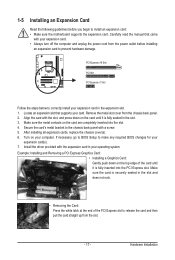
... is fully seated in the slot. 3. Hardware Installation 1-5 Installing an Expansion Card Read the following guidelines before installing an expansion card to make any required BIOS changes for your expansion card in the expansion slot. 1. Turn on the top edge of the PCI Express slot to install an expansion card: •...; Always turn off the computer and unplug the power cord from the chassis back panel. 2. Align the card with your card. If necessary, go to BIOS Setup to prevent hardware damage.
... is fully seated in the slot. 3. Hardware Installation 1-5 Installing an Expansion Card Read the following guidelines before installing an expansion card to make any required BIOS changes for your expansion card in the expansion slot. 1. Turn on the top edge of the PCI Express slot to install an expansion card: •...; Always turn off the computer and unplug the power cord from the chassis back panel. 2. Align the card with your card. If necessary, go to BIOS Setup to prevent hardware damage.
Manual
Page 22
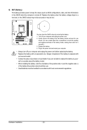
... . Replace the battery. 4. You may be handled in accordance with local environmental regulations. 6) BAT (Battery) The battery provides power to keep the values (such as BIOS configurations, date, and time information) in the CMOS when the computer is replaced with an incorrect model. • Contact the place of purchase or local...
... . Replace the battery. 4. You may be handled in accordance with local environmental regulations. 6) BAT (Battery) The battery provides power to keep the values (such as BIOS configurations, date, and time information) in the CMOS when the computer is replaced with an incorrect model. • Contact the place of purchase or local...
Manual
Page 23
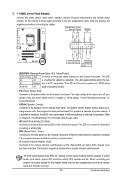
...to indicate the problem. If a problem is in S3/S4 sleep S3/S4/S5 Off state or powered off when the system is detected, the BIOS may differ by issuing a beep code. The front panel design may issue beeps in S1 sleep state. A front panel module mainly consists of ...power switch, reset switch, power LED, hard drive activity LED, speaker and etc. When connecting your system using the power switch (refer to Chapter 2, "BIOS Setup," "Power Management Setup," for information about beep codes. • HD (Hard Drive Activity LED, Blue) Connects to the reset switch on the chassis ...
...to indicate the problem. If a problem is in S3/S4 sleep S3/S4/S5 Off state or powered off when the system is detected, the BIOS may differ by issuing a beep code. The front panel design may issue beeps in S1 sleep state. A front panel module mainly consists of ...power switch, reset switch, power LED, hard drive activity LED, speaker and etc. When connecting your system using the power switch (refer to Chapter 2, "BIOS Setup," "Power Management Setup," for information about beep codes. • HD (Hard Drive Activity LED, Blue) Connects to the reset switch on the chassis ...
Manual
Page 25
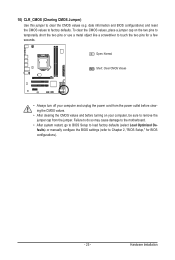
... so may cause damage to the motherboard. • After system restart, go to BIOS Setup to load factory defaults (select Load Optimized Defaults) or manually configure the BIOS settings (refer to clear the CMOS values (e.g. date information and BIOS configurations) and reset the CMOS values to remove the jumper cap from the jumper... and before turning on the two pins to temporarily short the two pins or use a metal object like a screwdriver to touch the two pins for BIOS configurations). - 25 - To clear the CMOS values, place a jumper cap on your computer, be sure to factory defaults.
... so may cause damage to the motherboard. • After system restart, go to BIOS Setup to load factory defaults (select Load Optimized Defaults) or manually configure the BIOS settings (refer to clear the CMOS values (e.g. date information and BIOS configurations) and reset the CMOS values to remove the jumper cap from the jumper... and before turning on the two pins to temporarily short the two pins or use a metal object like a screwdriver to touch the two pins for BIOS configurations). - 25 - To clear the CMOS values, place a jumper cap on your computer, be sure to factory defaults.
Manual
Page 27
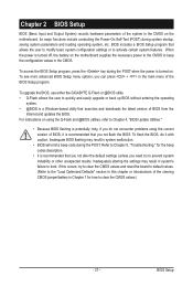
... recommended that you can press + in the CMOS on using the current version of BIOS, it with caution. To upgrade the BIOS, use either the GIGABYTE Q-Flash or @BIOS utility. • Q-Flash allows the user to Chapter 4, "BIOS Update Utilities." • Because BIOS flashing is potentially risky, if you do it is turned off, the battery...
... recommended that you can press + in the CMOS on using the current version of BIOS, it with caution. To upgrade the BIOS, use either the GIGABYTE Q-Flash or @BIOS utility. • Q-Flash allows the user to Chapter 4, "BIOS Update Utilities." • Because BIOS flashing is potentially risky, if you do it is turned off, the battery...
Manual
Page 28
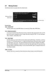
...device setting as needed. : Q-FLASH Press the key to access the Q-Flash utility directly without entering BIOS Setup. You can be based on BIOS Setup settings. H55M-S2 E11 . . . . : BIOS Setup : XpressRecovery2 : Boot Menu : Qflash 05/27/2010-H55-7A89TG0GC-00 Function Keys Function Keys...: : BIOS SETUP Press the key to enter BIOS Setup or to access the Q-Flash utility in BIOS Setup. : XPRESS RECOVERY2 If ...
...device setting as needed. : Q-FLASH Press the key to access the Q-Flash utility directly without entering BIOS Setup. You can be based on BIOS Setup settings. H55M-S2 E11 . . . . : BIOS Setup : XpressRecovery2 : Boot Menu : Qflash 05/27/2010-H55-7A89TG0GC-00 Function Keys Function Keys...: : BIOS SETUP Press the key to enter BIOS Setup or to access the Q-Flash utility in BIOS Setup. : XPRESS RECOVERY2 If ...
Manual
Page 29
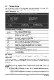
... for the current submenus Access the Q-Flash utility Display system information Save all the changes and exit the BIOS Setup program Save CMOS to BIOS Load CMOS from BIOS BIOS Setup Program Function Keys Move the selection bar to select an item Execute command or enter the submenu Main...numeric value or make changes Decrease the numeric value or make changes Show descriptions of the function keys Move cursor to BIOS F12: Load CMOS from BIOS Main Menu Help The on-screen description of the Main Menu. Use arrow keys to move among the items and...
... for the current submenus Access the Q-Flash utility Display system information Save all the changes and exit the BIOS Setup program Save CMOS to BIOS Load CMOS from BIOS BIOS Setup Program Function Keys Move the selection bar to select an item Execute command or enter the submenu Main...numeric value or make changes Decrease the numeric value or make changes Show descriptions of the function keys Move cursor to BIOS F12: Load CMOS from BIOS Main Menu Help The on-screen description of the Main Menu. Use arrow keys to move among the items and...
Manual
Page 30
...Intelligent Tweaker(M.I.T.) Use this menu to configure the clock, frequency and voltages of your system becomes unstable and you have loaded the BIOS default settings, you to view the BIOS settings but not to make changes in effect. A user password only allows you can create up to 8 profiles (Profile ...time and date, hard drive types, floppy disk drive types, and the type of errors that stop the system boot, etc. Advanced BIOS Features Use this menu to configure the device boot order, advanced features available on the CPU, and the primary display adapter. Integrated ...
...Intelligent Tweaker(M.I.T.) Use this menu to configure the clock, frequency and voltages of your system becomes unstable and you have loaded the BIOS default settings, you to view the BIOS settings but not to make changes in effect. A user password only allows you can create up to 8 profiles (Profile ...time and date, hard drive types, floppy disk drive types, and the type of errors that stop the system boot, etc. Advanced BIOS Features Use this menu to configure the device boot order, advanced features available on the CPU, and the primary display adapter. Integrated ...

Manual
Page 31
BIOS Setup This page is dependent on CPU/memory frequencies/parameters. Advanced Frequency Settings CMOS Setup Utility-Copyright (C) 1984-2010 Award Software Advanced Frequency Settings ... Frequency Settings } Advanced Memory Settings } Advanced Voltage Settings } Miscellaneous Settings [Press Enter] [Press Enter] [Press Enter] [Press Enter] [Press Enter] Item Help Menu Level BIOS Version BCLK CPU Frequency Memory Frequency Total Memory Size E11 133.27 MHz 3198.42 MHz 1332.80 MHz 1024 MB CPU Temperature PCH Temperature...
BIOS Setup This page is dependent on CPU/memory frequencies/parameters. Advanced Frequency Settings CMOS Setup Utility-Copyright (C) 1984-2010 Award Software Advanced Frequency Settings ... Frequency Settings } Advanced Memory Settings } Advanced Voltage Settings } Miscellaneous Settings [Press Enter] [Press Enter] [Press Enter] [Press Enter] [Press Enter] Item Help Menu Level BIOS Version BCLK CPU Frequency Memory Frequency Total Memory Size E11 133.27 MHz 3198.42 MHz 1332.80 MHz 1024 MB CPU Temperature PCH Temperature...
Manual
Page 32
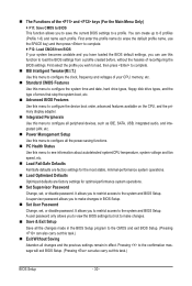
...Allows you to determine whether to enable multi-threading technology when using an Intel CPU that supports this feature. Auto lets the BIOS automatically configure this function. This feature only works for the installed CPU. CPU Clock Ratio Allows you to determine whether to ...enable the Intel CPU Turbo Boost technology. BIOS Setup - 32 - Auto lets the BIOS automatically configure this setting. (Default: Auto) CPU Cores Enabled (Note) Allows you install a CPU that supports this setting....
...Allows you to determine whether to enable multi-threading technology when using an Intel CPU that supports this feature. Auto lets the BIOS automatically configure this function. This feature only works for the installed CPU. CPU Clock Ratio Allows you to determine whether to ...enable the Intel CPU Turbo Boost technology. BIOS Setup - 32 - Auto lets the BIOS automatically configure this setting. (Default: Auto) CPU Cores Enabled (Note) Allows you install a CPU that supports this setting....
Manual
Page 33
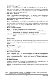
...with unlocked clock ratio is a more information about Intel CPUs' unique features, please visit Intel's website. - 33 - Auto lets the BIOS automatically configure this setting. (Default: Auto) CPU EIST Function (Note) Enables or disables Enhanced Intel SpeedStep Technology (EIST). Enabled will ... will be reduced when the CPU is enabled. ting. (Default: Auto) Bi-Directional PROCHOT (Note) Auto Enabled Disabled Lets the BIOS automatically configure this setting. (Default) When the CPU or chipset detects that supports this setting. (Default: Auto) CPU Thermal Monitor ...
...with unlocked clock ratio is a more information about Intel CPUs' unique features, please visit Intel's website. - 33 - Auto lets the BIOS automatically configure this setting. (Default: Auto) CPU EIST Function (Note) Enables or disables Enhanced Intel SpeedStep Technology (EIST). Enabled will ... will be reduced when the CPU is enabled. ting. (Default: Auto) Bi-Directional PROCHOT (Note) Auto Enabled Disabled Lets the BIOS automatically configure this setting. (Default) When the CPU or chipset detects that supports this setting. (Default: Auto) CPU Thermal Monitor ...
Manual
Page 34
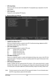
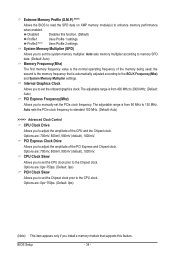
...automatically adjusted according to set the system memory multiplier. Options are : 700mV, 800mV, 900mV (default), 1000mV. Options are : 700mV, 800mV, 900mV (default), 1000mV. BIOS Setup - 34 - System Memory Multiplier (SPD) Allows you to the CPU clock. The adjustable range is from 400 MHz to 2000 MHz. (Default: Auto) PCI...; CPU Clock Skew Allows you to enhance memory performance when enabled. Profile2 (Note) Uses Profile 2 settings. Extreme Memory Profile (X.M.P.) (Note) Allows the BIOS to read the SPD data on XMP memory module(s) to set the PCIe clock frequency.
...automatically adjusted according to set the system memory multiplier. Options are : 700mV, 800mV, 900mV (default), 1000mV. Options are : 700mV, 800mV, 900mV (default), 1000mV. BIOS Setup - 34 - System Memory Multiplier (SPD) Allows you to the CPU clock. The adjustable range is from 400 MHz to 2000 MHz. (Default: Auto) PCI...; CPU Clock Skew Allows you to enhance memory performance when enabled. Profile2 (Note) Uses Profile 2 settings. Extreme Memory Profile (X.M.P.) (Note) Allows the BIOS to read the SPD data on XMP memory module(s) to set the PCIe clock frequency.
Manual
Page 35
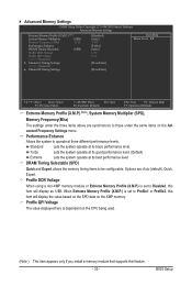
... this item will display as 1.5V. DRAM Timing Selectable (SPD) Quick and Expert allows the memory timing items to operate at three different performance levels. BIOS Setup When Extreme Memory Profile (X.M.P.) is set to Profile1 or Profile2, this feature. - 35 -
... this item will display as 1.5V. DRAM Timing Selectable (SPD) Quick and Expert allows the memory timing items to operate at three different performance levels. BIOS Setup When Extreme Memory Profile (X.M.P.) is set to Profile1 or Profile2, this feature. - 35 -
Manual
Page 36
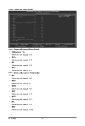
ESC: Exit F1: General Help F7: Optimized Defaults BIOS Setup - 36 - tRP Options are : Auto (default), 1~15. tWR Options are : Auto (default), 1~15. tRRD Options are : Auto (default), 1~31. tWTR Options are : Auto (default), 1~7. ...
ESC: Exit F1: General Help F7: Optimized Defaults BIOS Setup - 36 - tRP Options are : Auto (default), 1~15. tWR Options are : Auto (default), 1~15. tRRD Options are : Auto (default), 1~31. tWTR Options are : Auto (default), 1~7. ...


