
Manual
Page 4
... OptionalItems ...6 Box Contents ...6 GA-GC330UD Motherboard Layout 7 Block Diagram ...8 Chapter 1 Hardware Installation 9 1-1 Installation Precautions 9 1-2 Product Specifications 10 1-3 Installing the Memory 12 1-4 Back Panel Connectors 13 1-5 Internal Connectors 15 Chapter 2 BIOS Setup 23 2-1 Startup Screen 24 2-2 The Main Menu 25 2-3 Standard CMOS Features 27 2-4 Advanced BIOS Features 29 2-5 IntegratedPeripherals 31 2-6 Power Management Setup 33...
... OptionalItems ...6 Box Contents ...6 GA-GC330UD Motherboard Layout 7 Block Diagram ...8 Chapter 1 Hardware Installation 9 1-1 Installation Precautions 9 1-2 Product Specifications 10 1-3 Installing the Memory 12 1-4 Back Panel Connectors 13 1-5 Internal Connectors 15 Chapter 2 BIOS Setup 23 2-1 Startup Screen 24 2-2 The Main Menu 25 2-3 Standard CMOS Features 27 2-4 Advanced BIOS Features 29 2-5 IntegratedPeripherals 31 2-6 Power Management Setup 33...

Manual
Page 6
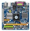
The box contents are for reference only. Optional Items 2-port USB 2.0 bracket (Part No. 12CR1-1UB030-5*R) 2-port SATA power cable (Part No. 12CF1-2SERPW-0*R) - 6 - Box Contents GA-GC330UD motherboard Motherboard driver disk User's Manual One IDE cable One SATA 3Gb/s cable I/O Shield • The box contents above are subject to change without notice. • The motherboard image is for reference only and the actual items shall depend on product package you obtain.
The box contents are for reference only. Optional Items 2-port USB 2.0 bracket (Part No. 12CR1-1UB030-5*R) 2-port SATA power cable (Part No. 12CF1-2SERPW-0*R) - 6 - Box Contents GA-GC330UD motherboard Motherboard driver disk User's Manual One IDE cable One SATA 3Gb/s cable I/O Shield • The box contents above are subject to change without notice. • The motherboard image is for reference only and the actual items shall depend on product package you obtain.

Manual
Page 9
.... • If you do not allow screws to come in a high-temperature environment. • Turning on the motherboard, make sure the power supply voltage has been set according to the local voltage standard. • Before using the product, please verify that all cables and...the motherboard, do not have it on top of an antistatic pad or within an electrostatic shielding container. • Before unplugging the power supply cable from the power outlet before installing or removing the motherboard or other hardware components. • Do not disassemble the onboard CPU and its components. ...
.... • If you do not allow screws to come in a high-temperature environment. • Turning on the motherboard, make sure the power supply voltage has been set according to the local voltage standard. • Before using the product, please verify that all cables and...the motherboard, do not have it on top of an antistatic pad or within an electrostatic shielding container. • Before unplugging the power supply cable from the power outlet before installing or removing the motherboard or other hardware components. • Do not disassemble the onboard CPU and its components. ...

Manual
Page 10
...up to 2 GB of system memory Support for DDR2 667(Note 2)/533 MHz memory module (Go to GIGABYTE's website for the latest memory support list.) Onboard Graphics Integrated in the North Bridge Audio ...power connector 1 x 4-pin ATX 12V power connector 1 x IDE connector 2 x SATA 3Gb/s connectors 1 x CPU fan header 1 x system fan header 1 x front panel header 1 x front panel audio header 2 x USB 2.0/1.1 headers 1 x chassis intrusion header 1 x power LED header GA-GC330UD...
...up to 2 GB of system memory Support for DDR2 667(Note 2)/533 MHz memory module (Go to GIGABYTE's website for the latest memory support list.) Onboard Graphics Integrated in the North Bridge Audio ...power connector 1 x 4-pin ATX 12V power connector 1 x IDE connector 2 x SATA 3Gb/s connectors 1 x CPU fan header 1 x system fan header 1 x front panel header 1 x front panel audio header 2 x USB 2.0/1.1 headers 1 x chassis intrusion header 1 x power LED header GA-GC330UD...

Manual
Page 12
...the left, place your memory module in only one direction. Step 2: The clips at both ends of the memory, push down on this motherboard. GA-GC330UD Motherboard - 12 - Follow the steps below to install a DDR2 DIMM on the memory and insert it can be installed in the memory socket.... the memory: • Make sure that the motherboard supports the memory. (Go to GIGABYTE's website for the latest memory support list.) • Always turn off the computer and unplug the power cord from the power outlet before you are unable to insert the memory, switch the direction. • DDR2...
...the left, place your memory module in only one direction. Step 2: The clips at both ends of the memory, push down on this motherboard. GA-GC330UD Motherboard - 12 - Follow the steps below to install a DDR2 DIMM on the memory and insert it can be installed in the memory socket.... the memory: • Make sure that the motherboard supports the memory. (Go to GIGABYTE's website for the latest memory support list.) • Always turn off the computer and unplug the power cord from the power outlet before you are unable to insert the memory, switch the direction. • DDR2...

Manual
Page 15
Unplug the power cord from the power outlet to prevent damage to the devices. • After installing the device and before connecting external devices: • First make sure the device cable has ...
Unplug the power cord from the power outlet to prevent damage to the devices. • After installing the device and before connecting external devices: • First make sure the device cable has ...

Manual
Page 16
... GND +5V GND +5V GND Power Good 5V SB(stand by +5V) +12V Pin No. 11 12 13 14 15 16 17 18 19 20 Definition 3.3V -12V GND PS_ON(soft On/Off) GND GND GND -5V +5V +5V GA-GC330UD Motherboard - 16 - The power connector possesses a foolproof design. 1/2)... ATX_12V/ATX (2x2 12V Power Connector and 2x12 Main Power Connector) With the use of the power connector, the power supply can supply enough stable power to the CPU. Connect the power supply cable to the power connector in the correct orientation...
... GND +5V GND +5V GND Power Good 5V SB(stand by +5V) +12V Pin No. 11 12 13 14 15 16 17 18 19 20 Definition 3.3V -12V GND PS_ON(soft On/Off) GND GND GND -5V +5V +5V GA-GC330UD Motherboard - 16 - The power connector possesses a foolproof design. 1/2)... ATX_12V/ATX (2x2 12V Power Connector and 2x12 Main Power Connector) With the use of the power connector, the power supply can supply enough stable power to the CPU. Connect the power supply cable to the power connector in the correct orientation...

Manual
Page 18
.../s cable to your SATA hard drive. 7) PWR_LED (System Power LED Header) This header can be used to connect a system power LED on when the system is in S1 sleep state. Pin No. System Status LED S0 On S1 Blinking S3/S4/S5 Off GA-GC330UD Motherboard - 18 - 6) SATA2_0/1 (SATA 3Gb/s Connectors,... Controlled by ICH7) The SATA connectors conform to indicate system power status. Pin No. The LED keeps blinking when the system is in S3/S4 sleep ...
.../s cable to your SATA hard drive. 7) PWR_LED (System Power LED Header) This header can be used to connect a system power LED on when the system is in S1 sleep state. Pin No. System Status LED S0 On S1 Blinking S3/S4/S5 Off GA-GC330UD Motherboard - 18 - 6) SATA2_0/1 (SATA 3Gb/s Connectors,... Controlled by ICH7) The SATA connectors conform to indicate system power status. Pin No. The LED keeps blinking when the system is in S3/S4 sleep ...

Manual
Page 19
... the battery holder, making them short for one . 8) BAT (Battery) The battery provides power to replace the battery by removing the battery: 1. Hardware Installation Turn off your computer and unplug the power cord. 2. Danger of explosion if the battery is replaced with an incorrect model. •...not able to keep the values (such as BIOS configurations, date, and time information) in the power cord and restart your computer. • Always turn off your computer and unplug the power cord before replacing the battery. • Replace the battery with an equivalent one minute. (Or ...
... the battery holder, making them short for one . 8) BAT (Battery) The battery provides power to replace the battery by removing the battery: 1. Hardware Installation Turn off your computer and unplug the power cord. 2. Danger of explosion if the battery is replaced with an incorrect model. •...not able to keep the values (such as BIOS configurations, date, and time information) in the power cord and restart your computer. • Always turn off your computer and unplug the power cord before replacing the battery. • Replace the battery with an equivalent one minute. (Or ...

Manual
Page 20
...your system using the power switch (refer to Chapter 2, "BIOS Setup," "Power Management Setup," for more information). • HD (Hard Drive Activity LED) Connects to the power status indicator on the chassis front panel. The LED is on when the hard drive is in S1 sleep state. GA-GC330UD Motherboard - 20 -... 9) F_PANEL (Front Panel Header) Connect the power switch, reset switch, and system status indicator on the chassis front panel to this header, make sure the...
...your system using the power switch (refer to Chapter 2, "BIOS Setup," "Power Management Setup," for more information). • HD (Hard Drive Activity LED) Connects to the power status indicator on the chassis front panel. The LED is on when the hard drive is in S1 sleep state. GA-GC330UD Motherboard - 20 -... 9) F_PANEL (Front Panel Header) Connect the power switch, reset switch, and system status indicator on the chassis front panel to this header, make sure the...

Manual
Page 21
... header. For HD Front Panel Audio: For AC'97 Front Panel Audio: 1 2 Pin No. 1 Definition MIC2_L Pin No. 1 Definition MIC 2 9 10 3 GND MIC2_R 2 GND 3 MIC Power 4 -ACZ_DET 4 NC 5 LINE2_R 5 Line Out (R) 6 FAUDIO_JD 6 NC 7 GND 7 NC 8 No Pin 8 No Pin 9 LINE2_L 9 Line Out (L) 10 FAUDIO_JD 10 NC • The front panel audio...
... header. For HD Front Panel Audio: For AC'97 Front Panel Audio: 1 2 Pin No. 1 Definition MIC2_L Pin No. 1 Definition MIC 2 9 10 3 GND MIC2_R 2 GND 3 MIC Power 4 -ACZ_DET 4 NC 5 LINE2_R 5 Line Out (R) 6 FAUDIO_JD 6 NC 7 GND 7 NC 8 No Pin 8 No Pin 9 LINE2_L 9 Line Out (L) 10 FAUDIO_JD 10 NC • The front panel audio...

Manual
Page 22
.... For purchasing the optional USB bracket, please contact the local dealer. 10 9 2 1 Pin No. 1 2 3 4 5 6 7 8 9 10 Definition Power (5V) Power (5V) USB DXUSB DYUSB DX+ USB DY+ GND GND No Pin NC • Do not plug the IEEE 1394 bracket (2x5-pin) cable into the...header. • Prior to installing the USB bracket, be sure to turn off your computer and unplug the power cord from the power outlet to prevent damage to USB 2.0/1.1 specification. Definition 1 Signal 1 2 GND GA-GC330UD Motherboard - 22 - This function requires a chassis with chassis intrusion detection design.
.... For purchasing the optional USB bracket, please contact the local dealer. 10 9 2 1 Pin No. 1 2 3 4 5 6 7 8 9 10 Definition Power (5V) Power (5V) USB DXUSB DYUSB DX+ USB DY+ GND GND No Pin NC • Do not plug the IEEE 1394 bracket (2x5-pin) cable into the...header. • Prior to installing the USB bracket, be sure to turn off your computer and unplug the power cord from the power outlet to prevent damage to USB 2.0/1.1 specification. Definition 1 Signal 1 2 GND GA-GC330UD Motherboard - 22 - This function requires a chassis with chassis intrusion detection design.
Manual
Page 23
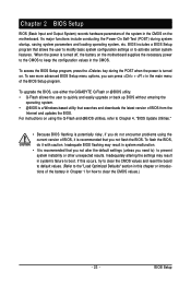
...parameters and loading operating system, etc. Inadequate BIOS flashing may result in Chapter 1 for how to boot. To upgrade the BIOS, use either the GIGABYTE Q-Flash or @BIOS utility. • Q-Flash allows the user to prevent system instability or other unexpected results. For instructions on . BIOS Setup ...and reset the board to default values. (Refer to the "Load Optimized Defaults" section in the CMOS on the motherboard supplies the necessary power to the CMOS to activate certain system features. BIOS includes a BIOS Setup program that you can press + in the main menu of the...
...parameters and loading operating system, etc. Inadequate BIOS flashing may result in Chapter 1 for how to boot. To upgrade the BIOS, use either the GIGABYTE Q-Flash or @BIOS utility. • Q-Flash allows the user to prevent system instability or other unexpected results. For instructions on . BIOS Setup ...and reset the board to default values. (Refer to the "Load Optimized Defaults" section in the CMOS on the motherboard supplies the necessary power to the CMOS to activate certain system features. BIOS includes a BIOS Setup program that you can press + in the main menu of the...

Manual
Page 26
...Setup Save all the changes made in the BIOS Setup program to the CMOS and exit BIOS Setup. (Pressing can also carry out this task.) GA-GC330UD Motherboard - 26 - A supervisor password allows you to view the BIOS settings but not to make changes in BIOS Setup. Set User... Integrated Peripherals Use this menu to configure all peripheral devices, such as IDE, SATA, USB, integrated audio, and integrated LAN, etc. Power Management Setup Use this menu to configure all changes and the previous settings remain in effect. It allows you to restrict access to configure the...
...Setup Save all the changes made in the BIOS Setup program to the CMOS and exit BIOS Setup. (Pressing can also carry out this task.) GA-GC330UD Motherboard - 26 - A supervisor password allows you to view the BIOS settings but not to make changes in BIOS Setup. Set User... Integrated Peripherals Use this menu to configure all peripheral devices, such as IDE, SATA, USB, integrated audio, and integrated LAN, etc. Power Management Setup Use this menu to configure all changes and the previous settings remain in effect. It allows you to restrict access to configure the...

Manual
Page 33
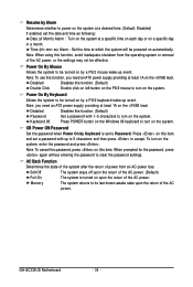
... a PCI or PCIe device. In S3 sleep state, the system appears to be off and consumes less power than 4 seconds, the system will be turned off the computer in a low power mode. Instant-Off Press the power button and then the system will enter suspend mode. Note: To use this function, you need... providing at any time. In S1 sleep state, the system appears suspended and stays in MS-DOS mode using the power button. The system can be awakened from an ACPI sleep state by a wake-up signal from a modem that supports wake-up device or event, the ...
... a PCI or PCIe device. In S3 sleep state, the system appears to be off and consumes less power than 4 seconds, the system will be turned off the computer in a low power mode. Instant-Off Press the power button and then the system will enter suspend mode. Note: To use this function, you need... providing at any time. In S1 sleep state, the system appears suspended and stays in MS-DOS mode using the power button. The system can be awakened from an ACPI sleep state by a wake-up signal from a modem that supports wake-up device or event, the ...
Manual
Page 34
...a PS/2 keyboard wake-up event. Note: you need an ATX power supply providing at which the system will be turned on automatically. Note: To cancel the password, press on the +5VSB lead. GA-GC330UD Motherboard - 34 - Note: To use this function, avoid inadequate shutdown... from an AC power loss. Disabled Disables this item. When prompted for the password, press again without entering the...
...a PS/2 keyboard wake-up event. Note: you need an ATX power supply providing at which the system will be turned on automatically. Note: To cancel the password, press on the +5VSB lead. GA-GC330UD Motherboard - 34 - Note: To use this function, avoid inadequate shutdown... from an AC power loss. Disabled Disables this item. When prompted for the password, press again without entering the...

Manual
Page 41
... saves the changes to the BIOS Setup Main Menu. 2-14 Exit Without Saving Standard CMOS Features Advanced BIOS Features Integrated Peripherals Power Management Setup PnP/PCI Configurations PC Health Status Frequency/Voltage Control Load Fail-Safe Defaults Load Optimized Defaults Set Supervisor Password Set...
... saves the changes to the BIOS Setup Main Menu. 2-14 Exit Without Saving Standard CMOS Features Advanced BIOS Features Integrated Peripherals Power Management Setup PnP/PCI Configurations PC Health Status Frequency/Voltage Control Load Fail-Safe Defaults Load Optimized Defaults Set Supervisor Password Set...

Manual
Page 51
.... Make sure the BIOS update file matches your system. appears, press to select Update BIOS from Drive Sa0vefilBeI(Os)SfotounDdrive :Move ESC:Reset :Power Off Total size : 0 Free size : 0 3. Save BIOS to Drive Please:Mproevses any key to return to access Q-Flash. ...Data Enable !! Updating the BIOS When updating the BIOS, choose the location where the BIOS file is complete, press any keEyStCo:Rcoensetitnue F10:Power Off - 51 - The monitor will display the update process. • Do not turn off or restart the system when the system ...
.... Make sure the BIOS update file matches your system. appears, press to select Update BIOS from Drive Sa0vefilBeI(Os)SfotounDdrive :Move ESC:Reset :Power Off Total size : 0 Free size : 0 3. Save BIOS to Drive Please:Mproevses any key to return to access Q-Flash. ...Data Enable !! Updating the BIOS When updating the BIOS, choose the location where the BIOS file is complete, press any keEyStCo:Rcoensetitnue F10:Power Off - 51 - The monitor will display the update process. • Do not turn off or restart the system when the system ...

Manual
Page 52
...restarts. CMOS Setup Utility-Copyright (C) 1984-2009 Award Software Standard CMOS Features Advanced BIOS Features Integrated Peripherals Power Management Setup PnP/PCI Configurations PC Health Status Frequency/Voltage Control Esc: Quit F8: Q-Flash Load Fail-Safe Defaults...a BIOS update, so we recommend that you should see the new BIOS version is present on the POST screen. GA-GC330UD Motherboard - 52 - Select Load Optimized Defaults and press to enter BIOS Setup. Step 5: During the POST, press to load BIOS defaults....
...restarts. CMOS Setup Utility-Copyright (C) 1984-2009 Award Software Standard CMOS Features Advanced BIOS Features Integrated Peripherals Power Management Setup PnP/PCI Configurations PC Health Status Frequency/Voltage Control Esc: Quit F8: Q-Flash Load Fail-Safe Defaults...a BIOS update, so we recommend that you should see the new BIOS version is present on the POST screen. GA-GC330UD Motherboard - 52 - Select Load Optimized Defaults and press to enter BIOS Setup. Step 5: During the POST, press to load BIOS defaults....
Manual
Page 53
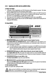
...Click Save Current BIOS to complete. Before You Begin: 1. Do not use the G.O.M. (GIGABYTE Online Management) function when using @BIOS. 4. screen instructions to save the BIOS update file obtained from GIGABYTE's website and follow the instruc- Make sure that is not present on the @BIOS ... NOT interrupt the Internet connection (for your motherboard is unable to complete. 3. If the BIOS update file for example, avoid a power loss or switching off the Internet). Update the BIOS Using the Internet Update Function: Click Update BIOS from an inadequate BIOS flashing. Load...
...Click Save Current BIOS to complete. Before You Begin: 1. Do not use the G.O.M. (GIGABYTE Online Management) function when using @BIOS. 4. screen instructions to save the BIOS update file obtained from GIGABYTE's website and follow the instruc- Make sure that is not present on the @BIOS ... NOT interrupt the Internet connection (for your motherboard is unable to complete. 3. If the BIOS update file for example, avoid a power loss or switching off the Internet). Update the BIOS Using the Internet Update Function: Click Update BIOS from an inadequate BIOS flashing. Load...


