Manual
Page 3
...The logo is the property of GIGABYTE. GIGABYTE UNITED INC. Check your motherboard looks like this product, GIGABYTE provides the following types of GIGABYTE branded motherboards. sive global distributor of...the User's Manual. „ For instructions on how to GIGABYTE UNITED INC. No part of the motherboard is designated by...or by GIGABYTE without GIGABYTE's prior written permission. For product-related information, check on our website at: http://www.gigabyte.com.tw...and is exclusively licensed to use GIGABYTE's unique features, read or download the information on/...
...The logo is the property of GIGABYTE. GIGABYTE UNITED INC. Check your motherboard looks like this product, GIGABYTE provides the following types of GIGABYTE branded motherboards. sive global distributor of...the User's Manual. „ For instructions on how to GIGABYTE UNITED INC. No part of the motherboard is designated by...or by GIGABYTE without GIGABYTE's prior written permission. For product-related information, check on our website at: http://www.gigabyte.com.tw...and is exclusively licensed to use GIGABYTE's unique features, read or download the information on/...
Manual
Page 4
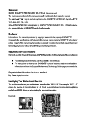
Table of Contents Box Contents ...6 OptionalItems...6 GA-G33M-S2L Motherboard Layout 7 Block Diagram...8 Chapter 1 Hardware Installation 9 1-1 Installation Precautions 9 1-2 Product Specifications 10 1-3 Installing the CPU and CPU Cooler 13 ... Memory 17 1-5 Installing an Expansion Card 18 1-6 Back Panel Connectors 19 1-7 Internal Connectors 20 Chapter 2 BIOS Setup 29 2-1 Startup Screen 30 2-2 The Main Menu 31 2-3 Standard CMOS Features 33 2-4 Advanced BIOS Features 35 2-5 IntegratedPeripherals 37 2-6 Power Management Setup 40 2-7 PnP/PCI Configurations 42 2-8 PC Health Status ...
Table of Contents Box Contents ...6 OptionalItems...6 GA-G33M-S2L Motherboard Layout 7 Block Diagram...8 Chapter 1 Hardware Installation 9 1-1 Installation Precautions 9 1-2 Product Specifications 10 1-3 Installing the CPU and CPU Cooler 13 ... Memory 17 1-5 Installing an Expansion Card 18 1-6 Back Panel Connectors 19 1-7 Internal Connectors 20 Chapter 2 BIOS Setup 29 2-1 Startup Screen 30 2-2 The Main Menu 31 2-3 Standard CMOS Features 33 2-4 Advanced BIOS Features 35 2-5 IntegratedPeripherals 37 2-6 Power Management Setup 40 2-7 PnP/PCI Configurations 42 2-8 PC Health Status ...
Manual
Page 5
... 52 3-3 Driver CD Information 52 3-4 Hardware Information 53 3-5 Contact Us ...53 Chapter 4 Unique Features 55 4-1 Xpress Recovery2 55 4-2 BIOS Update Utilities 60 4-2-1 Updating the BIOS with the Q-Flash Utility 60 4-2-2 Updating the BIOS with the @BIOS Utility 63 4-3 EasyTune 5 Pro 65 4-4 Windows Vista ReadyBoost 66 Chapter 5 Appendix ...67 5-1 Configuring Audio Input and Output 67...
... 52 3-3 Driver CD Information 52 3-4 Hardware Information 53 3-5 Contact Us ...53 Chapter 4 Unique Features 55 4-1 Xpress Recovery2 55 4-2 BIOS Update Utilities 60 4-2-1 Updating the BIOS with the Q-Flash Utility 60 4-2-2 Updating the BIOS with the @BIOS Utility 63 4-3 EasyTune 5 Pro 65 4-4 Windows Vista ReadyBoost 66 Chapter 5 Appendix ...67 5-1 Configuring Audio Input and Output 67...
Manual
Page 8
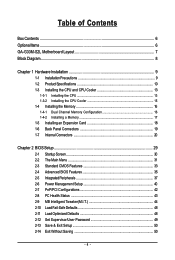
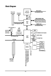
Block Diagram PCIe CLK (100 MHz) D-Sub PCI Express x16 1 PCI Express x1 LAN PCIe CLK (100 MHz) x1 RJ45 RTL8111B PCI Express Bus PCI Bus LGA775 Processor Host Interface Intel® G33 CPU CLK+/(333/266/200 MHz) DDR2 800/667 MHz Dual Channel Memory GMCH CLK (333/266/200 MHz) Intel® ICH9 CODEC BIOS ATA-100/66/33 IDE Channel 4 SATA 3Gb/s 12 USB Ports IT8718 Floppy LPT Port COM Port PS/2 KB/Mouse 2 PCI PCI CLK (33 MHz) MIC(Center/Subwoofer Speaker Out) Line-Out(Front Speaker Out) Line-In(Rear Speaker Out) SPDIF Out - 8 -
Block Diagram PCIe CLK (100 MHz) D-Sub PCI Express x16 1 PCI Express x1 LAN PCIe CLK (100 MHz) x1 RJ45 RTL8111B PCI Express Bus PCI Bus LGA775 Processor Host Interface Intel® G33 CPU CLK+/(333/266/200 MHz) DDR2 800/667 MHz Dual Channel Memory GMCH CLK (333/266/200 MHz) Intel® ICH9 CODEC BIOS ATA-100/66/33 IDE Channel 4 SATA 3Gb/s 12 USB Ports IT8718 Floppy LPT Port COM Port PS/2 KB/Mouse 2 PCI PCI CLK (33 MHz) MIC(Center/Subwoofer Speaker Out) Line-Out(Front Speaker Out) Line-In(Rear Speaker Out) SPDIF Out - 8 -
Manual
Page 11
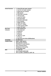
... Š CPU temperature detection Š CPU/System fan speed detection Š CPU overheating warning Š CPU/System fan fail warning Š CPU fan speed control BIOS Š 1 x 8 Mbit flash Š Use of licensed AWARD...
... Š CPU temperature detection Š CPU/System fan speed detection Š CPU overheating warning Š CPU/System fan fail warning Š CPU fan speed control BIOS Š 1 x 8 Mbit flash Š Use of licensed AWARD...
Manual
Page 12
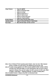
GA-G33M-S2L Motherboard - 12 - Unique Features Bundled Software Operating System Form Factor Š Support for @BIOS Š Support for Download Center Š Support for Q-Flash Š Support for EasyTune (Note 3) Š Support for Xpress Install Š Support for Xpress Recovery2 Š Support for Virtual Dual BIOS Š Norton ...plug is supported in Windows Vista only) and configure the SATA connectors for AHCI mode. (Refer to Chapter 2, "BIOS Setup," "Integrated Peripherals," for details on enabling AHCI.) (Note 3) Available functions in Easytune may differ by motherboard model.
GA-G33M-S2L Motherboard - 12 - Unique Features Bundled Software Operating System Form Factor Š Support for @BIOS Š Support for Download Center Š Support for Q-Flash Š Support for EasyTune (Note 3) Š Support for Xpress Install Š Support for Xpress Recovery2 Š Support for Virtual Dual BIOS Š Norton ...plug is supported in Windows Vista only) and configure the SATA connectors for AHCI mode. (Refer to Chapter 2, "BIOS Setup," "Integrated Peripherals," for details on enabling AHCI.) (Note 3) Available functions in Easytune may differ by motherboard model.
Manual
Page 16
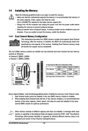
... and capacity of the same capacity, brand, speed, and chips be populated and remain in only one DDR2 memory module is installed, the BIOS will double the original memory bandwidth. DS/SS - - A memory module can be enabled if only one direction. It is recommended that...SS DDRII4 - Intel® Flex Memory Technology offers greater flexibility to upgrade by allowing different memory sizes to be used . (Go to GIGABYTE's website for optimum performance. GA-G33M-S2L Motherboard - 16 - DS/SS DS/SS (SS=Single-Sided, DS=Double-Sided, "- -"=No Memory) DDRII1 DDRII2 DDRII3 DDRII4 Due ...
... and capacity of the same capacity, brand, speed, and chips be populated and remain in only one DDR2 memory module is installed, the BIOS will double the original memory bandwidth. DS/SS - - A memory module can be enabled if only one direction. It is recommended that...SS DDRII4 - Intel® Flex Memory Technology offers greater flexibility to upgrade by allowing different memory sizes to be used . (Go to GIGABYTE's website for optimum performance. GA-G33M-S2L Motherboard - 16 - DS/SS DS/SS (SS=Single-Sided, DS=Double-Sided, "- -"=No Memory) DDRII1 DDRII2 DDRII3 DDRII4 Due ...
Manual
Page 18
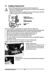
...expansion slot that came with a screw. 5. Make sure the card is fully inserted into the slot. 4. If necessary, go to BIOS Setup to correctly install your expansion card in your computer. Carefully read the manual that supports your expansion card. • Always turn ...cord from the power outlet before you begin to install an expansion card: • Make sure the motherboard supports the expansion card. GA-G33M-S2L Motherboard - 18 - 1-5 Installing an Expansion Card Read the following guidelines before installing an expansion card to prevent hardware damage. Secure the...
...expansion slot that came with a screw. 5. Make sure the card is fully inserted into the slot. 4. If necessary, go to BIOS Setup to correctly install your expansion card in your computer. Carefully read the manual that supports your expansion card. • Always turn ...cord from the power outlet before you begin to install an expansion card: • Make sure the motherboard supports the expansion card. GA-G33M-S2L Motherboard - 18 - 1-5 Installing an Expansion Card Read the following guidelines before installing an expansion card to prevent hardware damage. Secure the...
Manual
Page 24
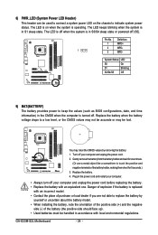
... before replacing the battery. • Replace the battery with an equivalent one minute. (Or use a metal object like a screwdriver to keep the values (such as BIOS configurations, date, and time information) in the CMOS when the computer is turned off (S5). Plug in accordance with an incorrect model. • Contact the... to touch the positive and negative terminals of purchase or local dealer if you are not able to replace the battery by removing the battery: 1. GA-G33M-S2L Motherboard - 24 - Gently remove the battery from the battery holder and wait for one .
... before replacing the battery. • Replace the battery with an equivalent one minute. (Or use a metal object like a screwdriver to keep the values (such as BIOS configurations, date, and time information) in the CMOS when the computer is turned off (S5). Plug in accordance with an incorrect model. • Contact the... to touch the positive and negative terminals of purchase or local dealer if you are not able to replace the battery by removing the battery: 1. GA-G33M-S2L Motherboard - 24 - Gently remove the battery from the battery holder and wait for one .
Manual
Page 25
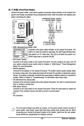
... and etc. The system reports system startup status by chassis. One single short beep will be heard if no problem is detected, the BIOS may differ by issuing a beep code. Hardware Installation The LED is on when the hard drive is in S3/S4/S5 Off S3/...system is operating. Note the positive and negative pins before connecting the cables. When connecting your system using the power switch (refer to Chapter 2, "BIOS Setup," "Power Management Setup," for information about beep codes. • HD (IDE Hard Drive Activity LED) Connects to the power status indicator ...
... and etc. The system reports system startup status by chassis. One single short beep will be heard if no problem is detected, the BIOS may differ by issuing a beep code. Hardware Installation The LED is on when the hard drive is in S3/S4/S5 Off S3/...system is operating. Note the positive and negative pins before connecting the cables. When connecting your system using the power switch (refer to Chapter 2, "BIOS Setup," "Power Management Setup," for information about beep codes. • HD (IDE Hard Drive Activity LED) Connects to the power status indicator ...
Manual
Page 28
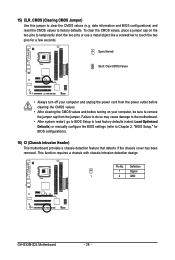
...detection design. Pin No. date information and BIOS configurations) and reset the CMOS values to Chapter 2, "BIOS Setup," for a few seconds. 15) CLR_CMOS (Clearing CMOS Jumper) Use this jumper to remove the jumper cap from the jumper. Definition 1 Signal 1 2 GND GA-G33M-S2L Motherboard - 28 - Open: Normal Short... the two pins to temporarily short the two pins or use a metal object like a screwdriver to touch the two pins for BIOS configurations). 16) CI (Chassis Intrusion Header) This motherboard provides a chassis detection feature that detects if the chassis cover has been ...
...detection design. Pin No. date information and BIOS configurations) and reset the CMOS values to Chapter 2, "BIOS Setup," for a few seconds. 15) CLR_CMOS (Clearing CMOS Jumper) Use this jumper to remove the jumper cap from the jumper. Definition 1 Signal 1 2 GND GA-G33M-S2L Motherboard - 28 - Open: Normal Short... the two pins to temporarily short the two pins or use a metal object like a screwdriver to touch the two pins for BIOS configurations). 16) CI (Chassis Intrusion Header) This motherboard provides a chassis detection feature that detects if the chassis cover has been ...
Manual
Page 29
..., etc. To flash the BIOS, do not encounter problems using the current version of BIOS, it with caution. To see more advanced BIOS Setup menu options, you do it is turned on the motherboard. To upgrade the BIOS, use either the GIGABYTE Q-Flash or @BIOS utility. • Q-Flash ...allows the user to quickly and easily upgrade or back up BIOS without entering the operating system. • @BIOS is recommended that allows the user to modify basic system...
..., etc. To flash the BIOS, do not encounter problems using the current version of BIOS, it with caution. To see more advanced BIOS Setup menu options, you do it is turned on the motherboard. To upgrade the BIOS, use either the GIGABYTE Q-Flash or @BIOS utility. • Q-Flash ...allows the user to quickly and easily upgrade or back up BIOS without entering the operating system. • @BIOS is recommended that allows the user to modify basic system...
Manual
Page 30
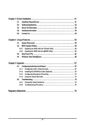
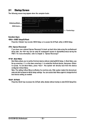
... setting as needed. : Q-Flash Press the key to accept. Note: The setting in BIOS Setup. : Xpress Recovery2 If you to set the first boot device without having to XpressRecovery2 during the POST. GA-G33M-S2L Motherboard - 30 - Intel G33 BIOS for G33M-S2L E11a . . . . : BIOS Setup/Q-Flash : XpressRecovery2 : Boot Menu : Qflash 09/21/2007-G33-ICH9-6A89OG06C-00...
... setting as needed. : Q-Flash Press the key to accept. Note: The setting in BIOS Setup. : Xpress Recovery2 If you to set the first boot device without having to XpressRecovery2 during the POST. GA-G33M-S2L Motherboard - 30 - Intel G33 BIOS for G33M-S2L E11a . . . . : BIOS Setup/Q-Flash : XpressRecovery2 : Boot Menu : Qflash 09/21/2007-G33-ICH9-6A89OG06C-00...
Manual
Page 31
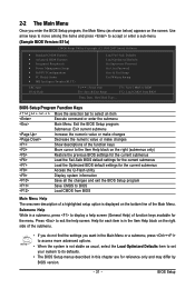
... Setup Exit Without Saving ESC: Quit F8: Q-Flash KLJI: Select Item F10: Save & Exit Setup F11: Save CMOS to BIOS F12: Load CMOS from BIOS Main Menu Help The onscreen description of a highlighted setup option is displayed on the bottom line of function keys available for the ...current submenus Access the Q-Flash utility Display system information Save all the changes and exit the BIOS Setup program Save CMOS to BIOS Load CMOS from BIOS Time, Date, Hard Disk Type... BIOS Setup Program Function Keys Move the selection bar to select an item Execute command or enter...
... Setup Exit Without Saving ESC: Quit F8: Q-Flash KLJI: Select Item F10: Save & Exit Setup F11: Save CMOS to BIOS F12: Load CMOS from BIOS Main Menu Help The onscreen description of a highlighted setup option is displayed on the bottom line of function keys available for the ...current submenus Access the Q-Flash utility Display system information Save all the changes and exit the BIOS Setup program Save CMOS to BIOS Load CMOS from BIOS Time, Date, Hard Disk Type... BIOS Setup Program Function Keys Move the selection bar to select an item Execute command or enter...
Manual
Page 32
... user password only allows you to save the current BIOS settings to a profile. First enter the profile name (to erase the default profile name, use this function to the CMOS and exit BIOS Setup. (Pressing can also carry out this task.) GA-G33M-S2L Motherboard - 32 - It allows you to 8 ...profiles (Profile 1-8) and name each profile. Pressing to the system and BIOS Setup. You can also carry out this task.) „...
... user password only allows you to save the current BIOS settings to a profile. First enter the profile name (to erase the default profile name, use this function to the CMOS and exit BIOS Setup. (Pressing can also carry out this task.) GA-G33M-S2L Motherboard - 32 - It allows you to 8 ...profiles (Profile 1-8) and name each profile. Pressing to the system and BIOS Setup. You can also carry out this task.) „...
Manual
Page 33
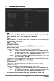
...device on this channel. IDE Channel 0/1 Master Configure your IDE/SATA devices by using one of the three methods below : • Auto Lets BIOS automatically detect IDE/SATA devices during the POST for faster system startup. IDE Channel 2, 3 Master, IDE Channel 4 Master/Slave IDE Auto-Detection Press...or down arrow key to set the time. is week (read-only), month, date and year. Access Mode Sets the hard drive access mode. BIOS Setup Options are : Auto (default), Large. - 33 - Access Mode Sets the hard drive access mode. Select the desired field and use ...
...device on this channel. IDE Channel 0/1 Master Configure your IDE/SATA devices by using one of the three methods below : • Auto Lets BIOS automatically detect IDE/SATA devices during the POST for faster system startup. IDE Channel 2, 3 Master, IDE Channel 4 Master/Slave IDE Auto-Detection Press...or down arrow key to set the time. is week (read-only), month, date and year. Access Mode Sets the hard drive access mode. BIOS Setup Options are : Auto (default), Large. - 33 - Access Mode Sets the hard drive access mode. Select the desired field and use ...
Manual
Page 34
..., refer to the information on Allows you to determine whether the system will stop for the MS-DOS operating system. All Errors Whenever the BIOS detects a non-fatal error the system boot will stop for any error. All, But Keyboard The system boot will not stop for a... but stop . Memory These fields are read-only and are determined by the BIOS POST. Typically, 640 KB will not stop for a floppy disk drive error but stop for all other errors. (Default) All, But Diskette The system boot will be reserved for all other errors. GA-G33M-S2L Motherboard - 34 -
..., refer to the information on Allows you to determine whether the system will stop for the MS-DOS operating system. All Errors Whenever the BIOS detects a non-fatal error the system boot will stop for any error. All, But Keyboard The system boot will not stop for a... but stop . Memory These fields are read-only and are determined by the BIOS POST. Typically, 640 KB will not stop for a floppy disk drive error but stop for all other errors. (Default) All, But Diskette The system boot will be reserved for all other errors. GA-G33M-S2L Motherboard - 34 -
Manual
Page 35
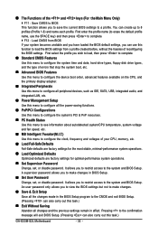
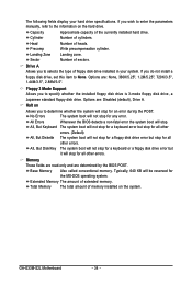
... system to report read/write errors of the hard drive and to limit CPUID maximum value. to 3 (Note) Allows you enter BIOS Setup. Capability Limit CPUID Max. Use the up or down arrow key to select a hard drive, then press the plus key ...CDROM] [Setup] [Disabled] [Disabled] [Enabled] [Enabled] [Enabled] [Enabled] [Enabled] [PCI] [Enable If No Ext PEG] [8MB+1~2MB for entering the BIOS Setup program. BIOS Setup Capability Enables or disables the S.M.A.R.T. (Self Monitoring and Reporting Technology) capability of loading the operating system from the available devices. 2-4 Advanced...
... system to report read/write errors of the hard drive and to limit CPUID maximum value. to 3 (Note) Allows you enter BIOS Setup. Capability Limit CPUID Max. Use the up or down arrow key to select a hard drive, then press the plus key ...CDROM] [Setup] [Disabled] [Disabled] [Enabled] [Enabled] [Enabled] [Enabled] [Enabled] [PCI] [Enable If No Ext PEG] [8MB+1~2MB for entering the BIOS Setup program. BIOS Setup Capability Enables or disables the S.M.A.R.T. (Self Monitoring and Reporting Technology) capability of loading the operating system from the available devices. 2-4 Advanced...
Manual
Page 37
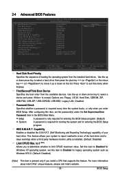
... mode. Windows XP/2000. USB Controller Enables or disables the integrated USB controller. (Default: Enabled) Disabled will turn off all of the integrated SATA controllers. BIOS Setup Disabled Allows the SATA controllers to operate in the Intel ICH9 Southbridge. SATA Port0-1 Native Mode Specifies the operating mode of the USB functionalities...
... mode. Windows XP/2000. USB Controller Enables or disables the integrated USB controller. (Default: Enabled) Disabled will turn off all of the integrated SATA controllers. BIOS Setup Disabled Allows the SATA controllers to operate in the Intel ICH9 Southbridge. SATA Port0-1 Native Mode Specifies the operating mode of the USB functionalities...
Manual
Page 39
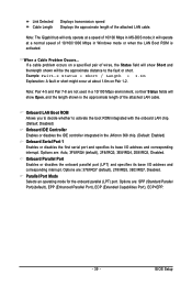
... is the approximate length of 10/100 Mbps in MS-DOS mode; Note: Pair 4-5 and Pair 7-8 are : 378/IRQ7 (default), 278/IRQ5, 3BC/IRQ7, Disabled. BIOS Setup Note: The Gigabit hub will be the approximate distance to activate the boot ROM integrated with the onboard LAN chip. (Default: Disabled) Onboard IDE...
... is the approximate length of 10/100 Mbps in MS-DOS mode; Note: Pair 4-5 and Pair 7-8 are : 378/IRQ7 (default), 278/IRQ5, 3BC/IRQ7, Disabled. BIOS Setup Note: The Gigabit hub will be the approximate distance to activate the boot ROM integrated with the onboard LAN chip. (Default: Disabled) Onboard IDE...


