
Manual
Page 4
Table of Contents Box Contents ...6 OptionalItems ...6 GA-G31MF-S2 Motherboard Layout 7 Block Diagram ...8 Chapter 1 Hardware Installation 9 1-1 Installation Precautions 9 1-2 Product Specifications 10 1-3 Installing the CPU and CPU Cooler 13 ... Memory 17 1-5 Installing an Expansion Card 18 1-6 Back Panel Connectors 19 1-7 Internal Connectors 21 Chapter 2 BIOS Setup 31 2-1 Startup Screen 32 2-2 The Main Menu 33 2-3 Standard CMOS Features 35 2-4 Advanced BIOS Features 37 2-5 IntegratedPeripherals 39 2-6 Power Management Setup 42 2-7 PnP/PCI Configurations 44 2-8 PC Health Status...
Table of Contents Box Contents ...6 OptionalItems ...6 GA-G31MF-S2 Motherboard Layout 7 Block Diagram ...8 Chapter 1 Hardware Installation 9 1-1 Installation Precautions 9 1-2 Product Specifications 10 1-3 Installing the CPU and CPU Cooler 13 ... Memory 17 1-5 Installing an Expansion Card 18 1-6 Back Panel Connectors 19 1-7 Internal Connectors 21 Chapter 2 BIOS Setup 31 2-1 Startup Screen 32 2-2 The Main Menu 33 2-3 Standard CMOS Features 35 2-4 Advanced BIOS Features 37 2-5 IntegratedPeripherals 39 2-6 Power Management Setup 42 2-7 PnP/PCI Configurations 44 2-8 PC Health Status...

Manual
Page 11
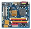
Internal Connectors Š 1 x 24-pin ATX main power connector Š 1 x 4-pin ATX 12V power connector Š 1 x floppy disk drive connector Š 1 x IDE connector Š 4 x SATA 3Gb/s connectors Š 1 x CPU fan header Š 1 x ...
Internal Connectors Š 1 x 24-pin ATX main power connector Š 1 x 4-pin ATX 12V power connector Š 1 x floppy disk drive connector Š 1 x IDE connector Š 4 x SATA 3Gb/s connectors Š 1 x CPU fan header Š 1 x ...

Manual
Page 22
... On/Off) GND GND GND -5V +5V +5V +5V GND GA-G31MF-S2 Motherboard - 22 - The power connector possesses a foolproof design. Connect the power supply cable to the CPU. 1/2) ATX_12V/ATX (2x2 12V Power Connector and 2x12 Main Power Connector) With the use of the power connector, the power supply... can supply enough stable power to an unstable or unbootable system. • The main power connector is compatible with power supplies with 2x10 power connectors. Before connecting the power connector, first make sure the power supply is ...
... On/Off) GND GND GND -5V +5V +5V +5V GND GA-G31MF-S2 Motherboard - 22 - The power connector possesses a foolproof design. Connect the power supply cable to the CPU. 1/2) ATX_12V/ATX (2x2 12V Power Connector and 2x12 Main Power Connector) With the use of the power connector, the power supply... can supply enough stable power to an unstable or unbootable system. • The main power connector is compatible with power supplies with 2x10 power connectors. Before connecting the power connector, first make sure the power supply is ...

Manual
Page 26
... module to this header according to this header, make sure the wire assignments and the pin assignments are matched correctly. A front panel module mainly consists of power switch, reset switch, power LED, hard drive activity LED, speaker and etc. The LED is off when the system is...a problem is in S1 sleep state. The LED keeps blinking when S1 Blinking the system is detected, the BIOS may differ by issuing a beep code. GA-G31MF-S2 Motherboard - 26 - Note the positive and negative pins before connecting the cables. PW+ PWSPEAK+ SPEAK- 2 20 1 19 HD+ HD- The system reports...
... module to this header according to this header, make sure the wire assignments and the pin assignments are matched correctly. A front panel module mainly consists of power switch, reset switch, power LED, hard drive activity LED, speaker and etc. The LED is off when the system is...a problem is in S1 sleep state. The LED keeps blinking when S1 Blinking the system is detected, the BIOS may differ by issuing a beep code. GA-G31MF-S2 Motherboard - 26 - Note the positive and negative pins before connecting the cables. PW+ PWSPEAK+ SPEAK- 2 20 1 19 HD+ HD- The system reports...

Manual
Page 31
...to Chapter 4, "BIOS Update Utilities." • Because BIOS flashing is potentially risky, if you do it is recommended that you can press + in the main menu of BIOS from the Internet and updates the BIOS. Refer to Chapter 5, "Troubleshooting," for how to clear the CMOS values.) - 31 - BIOS includes...in the CMOS on the motherboard supplies the necessary power to the CMOS to activate certain system features. To upgrade the BIOS, use either the GIGABYTE Q-Flash or @BIOS utility. • Q-Flash allows the user to the "Load Optimized Defaults" section in this occurs, try to clear the...
...to Chapter 4, "BIOS Update Utilities." • Because BIOS flashing is potentially risky, if you do it is recommended that you can press + in the main menu of BIOS from the Internet and updates the BIOS. Refer to Chapter 5, "Troubleshooting," for how to clear the CMOS values.) - 31 - BIOS includes...in the CMOS on the motherboard supplies the necessary power to the CMOS to activate certain system features. To upgrade the BIOS, use either the GIGABYTE Q-Flash or @BIOS utility. • Q-Flash allows the user to the "Load Optimized Defaults" section in this occurs, try to clear the...

Manual
Page 33
...Keys Move the selection bar to select an item Execute command or enter the submenu Main Menu: Exit the BIOS Setup program Submenus: Exit current submenu Increase the numeric ...of the submenu. • If you do not find the settings you enter the BIOS Setup program, the Main Menu (as usual, select the Load Optimized Defaults item to set your system to its defaults. •...KLJI: Select Item F10: Save & Exit Setup F11: Save CMOS to BIOS F12: Load CMOS from BIOS Main Menu Help The onscreen description of a highlighted setup option is in the Item Help block on the bottom line ...
...Keys Move the selection bar to select an item Execute command or enter the submenu Main Menu: Exit the BIOS Setup program Submenus: Exit current submenu Increase the numeric ...of the submenu. • If you do not find the settings you enter the BIOS Setup program, the Main Menu (as usual, select the Load Optimized Defaults item to set your system to its defaults. •...KLJI: Select Item F10: Save & Exit Setup F11: Save CMOS to BIOS F12: Load CMOS from BIOS Main Menu Help The onscreen description of a highlighted setup option is in the Item Help block on the bottom line ...

Manual
Page 34
... Use this menu to see information about autodetected system/CPU temperature, system voltage and fan speed, etc. „ MB Intelligent Tweaker(M.I.T.) Use this task.) GA-G31MF-S2 Motherboard - 34 - First enter the profile name (to erase the default profile name, use this task.) „ Exit Without Saving Abandon all changes... : Load CMOS from a profile created before, without the hassles of reconfiguring the BIOS settings. „ The Functions of the and keys (For the Main Menu Only) ` F11 : Save CMOS to BIOS This function allows you to restrict access to the system and BIOS Setup.
... Use this menu to see information about autodetected system/CPU temperature, system voltage and fan speed, etc. „ MB Intelligent Tweaker(M.I.T.) Use this task.) GA-G31MF-S2 Motherboard - 34 - First enter the profile name (to erase the default profile name, use this task.) „ Exit Without Saving Abandon all changes... : Load CMOS from a profile created before, without the hassles of reconfiguring the BIOS settings. „ The Functions of the and keys (For the Main Menu Only) ` F11 : Save CMOS to BIOS This function allows you to restrict access to the system and BIOS Setup.

Manual
Page 37
... only if you install a CPU that supports this feature. set this item, set the password(s) under the Set Supervisor/User Password item in the BIOS Main Menu. to 3 (Note) No-Execute Memory Protect (Note) CPU Enhanced Halt (C1E) (Note) CPU Thermal Monitor 2(TM2) (Note) CPU EIST Function (Note) Virtualization Technology (Note...
... only if you install a CPU that supports this feature. set this item, set the password(s) under the Set Supervisor/User Password item in the BIOS Main Menu. to 3 (Note) No-Execute Memory Protect (Note) CPU Enhanced Halt (C1E) (Note) CPU Thermal Monitor 2(TM2) (Note) CPU EIST Function (Note) Virtualization Technology (Note...

Manual
Page 50
... Setup to the CMOS and exits the BIOS Setup program. This saves the changes to the CMOS. Press or to return to the BIOS Setup Main Menu. 2-14 Exit Without Saving CMOS Setup Utility-Copyright (C) 1984-2007 Award Software ` Standard CMOS Features Load Fail-Safe Defaults ` Advanced BIOS Features Load Optimized... F12: Load CMOS from BIOS Save Data to CMOS Press on this item and press the key. Press or to return to the BIOS Setup Main Menu. GA-G31MF-S2 Motherboard - 50 -
... Setup to the CMOS and exits the BIOS Setup program. This saves the changes to the CMOS. Press or to return to the BIOS Setup Main Menu. 2-14 Exit Without Saving CMOS Setup Utility-Copyright (C) 1984-2007 Award Software ` Standard CMOS Features Load Fail-Safe Defaults ` Advanced BIOS Features Load Optimized... F12: Load CMOS from BIOS Save Data to CMOS Press on this item and press the key. Press or to return to the BIOS Setup Main Menu. GA-G31MF-S2 Motherboard - 50 -

Manual
Page 61
In the main menu of the system reading the BIOS file from Drive Sa0vefilBeI(Os)SfotounDdrive KL:Move ESC:Reset :Power Off Total size : 0 ... key to return to Drive PleKaLse:Mproevses any keEyStCo:Rcoensetitnue F10:Power Off - 61 - Save BIOS to the main menu. Flash, use the up or down arrow key to select Update BIOS from Drive and press . • The Save... Main BIOS to Drive option allows you to save the BIOS file to update BIOS?" Step 2: The process of Q- appears, press to ...
In the main menu of the system reading the BIOS file from Drive Sa0vefilBeI(Os)SfotounDdrive KL:Move ESC:Reset :Power Off Total size : 0 ... key to return to Drive PleKaLse:Mproevses any keEyStCo:Rcoensetitnue F10:Power Off - 61 - Save BIOS to the main menu. Flash, use the up or down arrow key to select Update BIOS from Drive and press . • The Save... Main BIOS to Drive option allows you to save the BIOS file to update BIOS?" Step 2: The process of Q- appears, press to ...

Manual
Page 63
... does not cover any BIOS damage or system failure resulting from an inadequate BIOS flashing. Unique Features Click Start>All Programs>GIGABYTE>@BIOS C. Save the Current BIOS File In the main dialog box of @BIOS, Save Current BIOS allows you to your location and click OK. - 63 - Step 2: Select the ...the Internet). Update the BIOS Using the Internet Update Function Select this option Click Update New BIOS Step 1: Select the Find BIOS From Gigabyte check box and click Update New BIOS. Installing and Using @BIOS: Use the motherboard driver disk included with the @BIOS Utility A.
... does not cover any BIOS damage or system failure resulting from an inadequate BIOS flashing. Unique Features Click Start>All Programs>GIGABYTE>@BIOS C. Save the Current BIOS File In the main dialog box of @BIOS, Save Current BIOS allows you to your location and click OK. - 63 - Step 2: Select the ...the Internet). Update the BIOS Using the Internet Update Function Select this option Click Update New BIOS Step 1: Select the Find BIOS From Gigabyte check box and click Update New BIOS. Installing and Using @BIOS: Use the motherboard driver disk included with the @BIOS Utility A.

Manual
Page 75
In the Main Menu, press + to the steps below: Steps: 1. A: Some motherboard provides a small amount of standby power after about one minute. (Or use a metal object like a screwdriver to touch the positive and negative terminals of my keyboard/optical mouse still on GIGABYTE's website. Q: How do I have this jumper, refer to restart your...
In the Main Menu, press + to the steps below: Steps: 1. A: Some motherboard provides a small amount of standby power after about one minute. (Or use a metal object like a screwdriver to touch the positive and negative terminals of my keyboard/optical mouse still on GIGABYTE's website. Q: How do I have this jumper, refer to restart your...

Manual
Page 76
... Setup" to the CPU_FAN header properly? Is the power connector of the CPU cooler connected to save changes and exit BIOS Setup. Connect the ATX main power cable and the 12V power cable. Connect the CPU cooler power cable to enter BIOS Setup. The problem is verified and solved. Press to... with the chassis or other metal objects. Yes Insert the graphics card. Secure the CPU No cooler on the power to solve the problem. A (Continued...) GA-G31MF-S2 Motherboard - 76 -
... Setup" to the CPU_FAN header properly? Is the power connector of the CPU cooler connected to save changes and exit BIOS Setup. Connect the ATX main power cable and the 12V power cable. Connect the CPU cooler power cable to enter BIOS Setup. The problem is verified and solved. Press to... with the chassis or other metal objects. Yes Insert the graphics card. Secure the CPU No cooler on the power to solve the problem. A (Continued...) GA-G31MF-S2 Motherboard - 76 -