Manual
Page 6
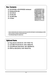
Box Contents GA-G31M-ES2L or GA-G31M-ES2C motherboard Motherboard driver disk User's Manual One IDE cable Two SATA cables I/O Shield • The box contents above are subject to change without notice. • The motherboard image is for reference only and the actual items shall depend on product package you obtain. Optional Items Floppy disk drive cable (Part No. 12CF1-1FD001-7*R) 2-port USB 2.0 bracket (Part No. 12CR1-1UB030-5*R) 2-port SATA power cable (Part No. 12CF1-2SERPW-0*R) S/PDIF out cable (Part No. 12CR1-1SPOUT-0*R) - 6 - The box contents are for reference only.
Box Contents GA-G31M-ES2L or GA-G31M-ES2C motherboard Motherboard driver disk User's Manual One IDE cable Two SATA cables I/O Shield • The box contents above are subject to change without notice. • The motherboard image is for reference only and the actual items shall depend on product package you obtain. Optional Items Floppy disk drive cable (Part No. 12CF1-1FD001-7*R) 2-port USB 2.0 bracket (Part No. 12CR1-1UB030-5*R) 2-port SATA power cable (Part No. 12CF1-2SERPW-0*R) S/PDIF out cable (Part No. 12CR1-1SPOUT-0*R) - 6 - The box contents are for reference only.
Manual
Page 10
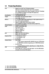
...GB of system memory (Note 1) Dual channel memory architecture Support for DDR2 800/667 MHz memory modules (Go to GIGABYTE's website for the latest memory support list.) Integrated in the North Bridge Realtek ALC883/888B codec High Definition...; iTE IT8718 chip: - 1 x floppy disk drive connector supporting up to 1 floppy disk drive Integrated in the South Bridge Up to 8 USB 2.0/1.1 ports (4 on the back panel, 4 via the USB brackets connected to the internal USB headers) Only for GA-G31M-ES2C. GA-G31M-ES2L/ES2C Motherboard - 10 -
...GB of system memory (Note 1) Dual channel memory architecture Support for DDR2 800/667 MHz memory modules (Go to GIGABYTE's website for the latest memory support list.) Integrated in the North Bridge Realtek ALC883/888B codec High Definition...; iTE IT8718 chip: - 1 x floppy disk drive connector supporting up to 1 floppy disk drive Integrated in the South Bridge Up to 8 USB 2.0/1.1 ports (4 on the back panel, 4 via the USB brackets connected to the internal USB headers) Only for GA-G31M-ES2C. GA-G31M-ES2L/ES2C Motherboard - 10 -
Manual
Page 11
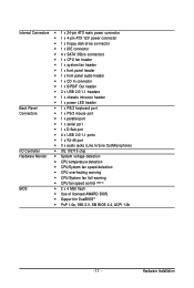
Hardware Installation Internal Connectors 1 x 24-pin ATX main power connector 1 x 4-pin ATX 12V power connector 1 x floppy disk drive connector 1 x IDE connector 4 x SATA 3Gb/s connectors 1 x CPU fan header 1 x system fan header 1 x front panel header 1 x front panel audio header &#...
Hardware Installation Internal Connectors 1 x 24-pin ATX main power connector 1 x 4-pin ATX 12V power connector 1 x floppy disk drive connector 1 x IDE connector 4 x SATA 3Gb/s connectors 1 x CPU fan header 1 x system fan header 1 x front panel header 1 x front panel audio header &#...
Manual
Page 13
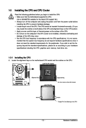
... beyond the standard specifications, please do so according to your hardware specifications including the CPU, graphics card, memory, hard drive, etc. 1-3-1 Installing the CPU A. mended that the motherboard supports the CPU. (Go to GIGABYTE's website for the peripherals. If you may occur. • Set the CPU host frequency in accordance with the...
... beyond the standard specifications, please do so according to your hardware specifications including the CPU, graphics card, memory, hard drive, etc. 1-3-1 Installing the CPU A. mended that the motherboard supports the CPU. (Go to GIGABYTE's website for the peripherals. If you may occur. • Set the CPU host frequency in accordance with the...
Manual
Page 19
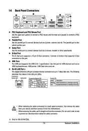
... LAN Port The Gigabit Ethernet LAN port provides Internet connection at up to connect devices such as an USB keyboard/mouse, USB printer, USB flash drive and etc. Hardware Installation The following describes the states of the LAN port LEDs. Only for USB devices such as a mouse, modem or other peripherals... from your device and then remove it from the connector. The parallel port is occurring • When removing the cable connected to this port for GA-G31M-ES2L. - 19 -
... LAN Port The Gigabit Ethernet LAN port provides Internet connection at up to connect devices such as an USB keyboard/mouse, USB printer, USB flash drive and etc. Hardware Installation The following describes the states of the LAN port LEDs. Only for USB devices such as a mouse, modem or other peripherals... from your device and then remove it from the connector. The parallel port is occurring • When removing the cable connected to this port for GA-G31M-ES2L. - 19 -
Manual
Page 20
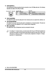
... Jack (Pink) The default Mic in devices such as an optical drive, walkman, etc. GA-G31M-ES2L/ES2C Motherboard - 20 - Line Out Jack (Green) The default line out jack. Use this audio jack for line in jack. Refer to this audio jack for GA-G31M-ES2C. To configure 7.1-channel audio, you need connect with the port of...
... Jack (Pink) The default Mic in devices such as an optical drive, walkman, etc. GA-G31M-ES2L/ES2C Motherboard - 20 - Line Out Jack (Green) The default line out jack. Use this audio jack for line in jack. Refer to this audio jack for GA-G31M-ES2C. To configure 7.1-channel audio, you need connect with the port of...

Manual
Page 23
...wire). The types of the connector and the floppy disk drive cable. Most fan headers possess a foolproof insertion design. Before connecting a floppy disk drive, be sure to locate pin 1 of floppy disk drives supported are not configuration jumper blocks. Overheating may result in... requires the use of different color. 33 1 34 2 - 23 - Hardware Installation For optimum heat dissipation, it in damage to connect a floppy disk drive. When connecting a fan cable, be installed inside the chassis. 1 CPU_FAN CPU_FAN : Pin No. 1 2 3 4 Definition GND +12V/Speed Control Sense...
...wire). The types of the connector and the floppy disk drive cable. Most fan headers possess a foolproof insertion design. Before connecting a floppy disk drive, be sure to locate pin 1 of floppy disk drives supported are not configuration jumper blocks. Overheating may result in... requires the use of different color. 33 1 34 2 - 23 - Hardware Installation For optimum heat dissipation, it in damage to connect a floppy disk drive. When connecting a fan cable, be installed inside the chassis. 1 CPU_FAN CPU_FAN : Pin No. 1 2 3 4 Definition GND +12V/Speed Control Sense...
Manual
Page 24
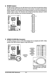
... No. 1 2 3 4 5 6 7 Definition GND TXP TXN GND RXN RXP GND GA-G31M-ES2L/ES2C Motherboard - 24 - If you wish to connect two IDE devices, remember to set the jumpers and the cabling according to the role of the SATA cable to your SATA hard drive. 6) IDE (IDE Connector) The IDE connector supports up to SATA...devices, read the instructions from the device manufacturers.) 40 39 2 1 7) SATAII0/1/2/3 (SATA 3Gb/s Connectors) The SATA connectors conform to two IDE devices such as hard drives and optical drives. Before attaching the IDE cable, locate the foolproof groove on the connector.
... No. 1 2 3 4 5 6 7 Definition GND TXP TXN GND RXN RXP GND GA-G31M-ES2L/ES2C Motherboard - 24 - If you wish to connect two IDE devices, remember to set the jumpers and the cabling according to the role of the SATA cable to your SATA hard drive. 6) IDE (IDE Connector) The IDE connector supports up to SATA...devices, read the instructions from the device manufacturers.) 40 39 2 1 7) SATAII0/1/2/3 (SATA 3Gb/s Connectors) The SATA connectors conform to two IDE devices such as hard drives and optical drives. Before attaching the IDE cable, locate the foolproof groove on the connector.
Manual
Page 26
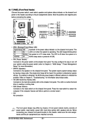
...freezes and fails to perform a normal restart. • NC: No connection The front panel design may issue beeps in different patterns to indicate the problem. GA-G31M-ES2L/ES2C Motherboard - 26 - Refer to Chapter 5, "Troubleshooting," for more information). • SPEAK (Speaker): Connects to the speaker on the chassis front panel....this header according to the pin assignments below. The LED is off when the system is operating. The LED is on when the hard drive is reading or writing data. • RES (Reset Switch): Connects to the reset switch on when the system is in S1 sleep ...
...freezes and fails to perform a normal restart. • NC: No connection The front panel design may issue beeps in different patterns to indicate the problem. GA-G31M-ES2L/ES2C Motherboard - 26 - Refer to Chapter 5, "Troubleshooting," for more information). • SPEAK (Speaker): Connects to the speaker on the chassis front panel....this header according to the pin assignments below. The LED is off when the system is operating. The LED is on when the hard drive is reading or writing data. • RES (Reset Switch): Connects to the reset switch on when the system is in S1 sleep ...
Manual
Page 27
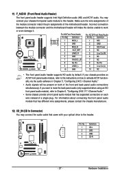
... an HD front panel audio module), refer to Chapter 5, "Configuring 2/4/5.1/7.1-Channel Audio." • Some chassis provide a front panel audio module that came with your optical drive to this header. Definition 1 CD-L 2 GND 3 GND 4 CD-R - 27 - Definition 2 10 1 MIC2_L Pin No. 1 Definition MIC 2 1 9 3 GND MIC2_R 2 GND 3 MIC Power 4 -ACZ_DET 4 NC 5 LINE2_R 5 Line...
... an HD front panel audio module), refer to Chapter 5, "Configuring 2/4/5.1/7.1-Channel Audio." • Some chassis provide a front panel audio module that came with your optical drive to this header. Definition 1 CD-L 2 GND 3 GND 4 CD-R - 27 - Definition 2 10 1 MIC2_L Pin No. 1 Definition MIC 2 1 9 3 GND MIC2_R 2 GND 3 MIC Power 4 -ACZ_DET 4 NC 5 LINE2_R 5 Line...
Manual
Page 32
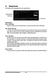
... computer boots. To exit Boot Menu, press . The system will still be used for one time only. In Boot Menu, use the up hard drive data using the motherboard driver disk, the key can access Boot Menu again to change the first boot device setting as needed. : Q-Flash Press the... to back up arrow key < > or the down arrow key< > to select the first boot device, then press to enter BIOS Setup first. GA-G31M-ES2L/ES2C Motherboard - 32 - You can be based on BIOS Setup settings. After system restart, the device boot order will directly boot from the device configured in...
... computer boots. To exit Boot Menu, press . The system will still be used for one time only. In Boot Menu, use the up hard drive data using the motherboard driver disk, the key can access Boot Menu again to change the first boot device setting as needed. : Q-Flash Press the... to back up arrow key < > or the down arrow key< > to select the first boot device, then press to enter BIOS Setup first. GA-G31M-ES2L/ES2C Motherboard - 32 - You can be based on BIOS Setup settings. After system restart, the device boot order will directly boot from the device configured in...
Manual
Page 34
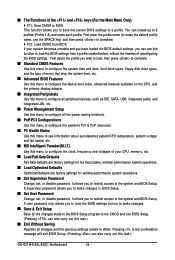
First enter the profile name (to erase the default profile name, use this task.) GA-G31M-ES2L/ES2C Motherboard - 34 - A user password only allows you to make changes. Save & Exit Setup Save all the changes made in the BIOS Setup program to ... profile you wish to load, then press to complete. Standard CMOS Features Use this menu to configure the system time and date, hard drive types, floppy disk drive types, and the type of errors that stop the system boot, etc. Advanced BIOS Features Use this menu to configure the device...
First enter the profile name (to erase the default profile name, use this task.) GA-G31M-ES2L/ES2C Motherboard - 34 - A user password only allows you to make changes. Save & Exit Setup Save all the changes made in the BIOS Setup program to ... profile you wish to load, then press to complete. Standard CMOS Features Use this menu to configure the system time and date, hard drive types, floppy disk drive types, and the type of errors that stop the system boot, etc. Advanced BIOS Features Use this menu to configure the device...

Manual
Page 35
...Detection Press to None so the system will skip the detection of the device during the POST for faster system startup. Extended IDE Drive Configure your IDE/SATA devices by using one of the two methods below : • Auto • None • Manual ... Channel 2 Master IDE Channel 2 Slave IDE Channel 3 Master IDE Channel 3 Slave [None] [None] [None] [None] [None] [None] Drive A Floppy 3 Mode Support [1.44M, 3.5"] [Disabled] Halt On [All, But Keyboard] Base Memory Extended Memory Total Memory 640K 510M 512M Move Enter: Select F5: Previous Values...
...Detection Press to None so the system will skip the detection of the device during the POST for faster system startup. Extended IDE Drive Configure your IDE/SATA devices by using one of the two methods below : • Auto • None • Manual ... Channel 2 Master IDE Channel 2 Slave IDE Channel 3 Master IDE Channel 3 Slave [None] [None] [None] [None] [None] [None] Drive A Floppy 3 Mode Support [1.44M, 3.5"] [Disabled] Halt On [All, But Keyboard] Base Memory Extended Memory Total Memory 640K 510M 512M Move Enter: Select F5: Previous Values...
Manual
Page 36
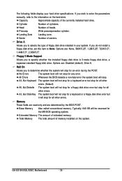
...The amount of the currently installed hard drive. Capacity Approximate capacity of extended memory. Landing Zone Landing zone. Options are : Disabled (default), Drive A. GA-G31M-ES2L/ES2C Motherboard - 36 - Total Memory The total amount of memory installed on the hard drive. Options are : None, 360K/5.25...Number of heads. Head Number of cylinders. Precomp Write precompensation cylinder. Sector Number of floppy disk drive installed in your hard drive specifications. If you to determine whether the system will be reserved for an error during the ...
...The amount of the currently installed hard drive. Capacity Approximate capacity of extended memory. Landing Zone Landing zone. Options are : Disabled (default), Drive A. GA-G31M-ES2L/ES2C Motherboard - 36 - Total Memory The total amount of memory installed on the hard drive. Options are : None, 360K/5.25...Number of heads. Head Number of cylinders. Precomp Write precompensation cylinder. Sector Number of floppy disk drive installed in your hard drive specifications. If you to determine whether the system will be reserved for an error during the ...
Manual
Page 37
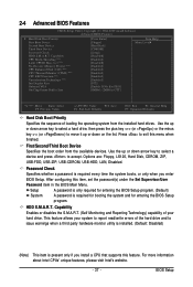
..., LS120, Hard Disk, CDROM, ZIP, USB-FDD, USB-ZIP, USB-CDROM, USB-HDD, LAN, Disabled. HDD S.M.A.R.T. This feature allows your hard drive. After configuring this item, set the password(s) under the Set Supervisor/User Password item in the BIOS Main Menu. For more information about Intel CPUs...: Exit F1: General Help F7: Optimized Defaults Hard Disk Boot Priority Specifies the sequence of your system to report read/write errors of the hard drive and to 3 (Note) No-Execute Memory Protect (Note) CPU Enhanced Halt (C1E) (Note) CPU Thermal Monitor 2(TM2) (Note) CPU EIST Function...
..., LS120, Hard Disk, CDROM, ZIP, USB-FDD, USB-ZIP, USB-CDROM, USB-HDD, LAN, Disabled. HDD S.M.A.R.T. This feature allows your hard drive. After configuring this item, set the password(s) under the Set Supervisor/User Password item in the BIOS Main Menu. For more information about Intel CPUs...: Exit F1: General Help F7: Optimized Defaults Hard Disk Boot Priority Specifies the sequence of your system to report read/write errors of the hard drive and to 3 (Note) No-Execute Memory Protect (Note) CPU Enhanced Halt (C1E) (Note) CPU Thermal Monitor 2(TM2) (Note) CPU EIST Function...

Manual
Page 41
..., this option will be used in MS-DOS. (Default: Disabled) Legacy USB storage detect Determines whether to detect USB storage devices, including USB flash drives and USB hard drives during the POST. (Default: Enabled) Azalia Codec Enables or disables the onboard audio function. (Default: Auto) If you wish to install a 3rd party...
..., this option will be used in MS-DOS. (Default: Disabled) Legacy USB storage detect Determines whether to detect USB storage devices, including USB flash drives and USB hard drives during the POST. (Default: Enabled) Azalia Codec Enables or disables the onboard audio function. (Default: Auto) If you wish to install a 3rd party...
Manual
Page 53
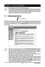
... the screen shot below. (If the driver Autorun screen does not appear automatically, go to My Computer, double-click the optical drive and execute the Run.exe program.) 3-1 Installing Chipset Drivers After inserting the driver disk, "Xpress Install" will continue to restart ... to install. • Please ignore the popup dialog box(es) (e.g. After the system restart, "Xpress Install" will automatically scan your optical drive. Chapter 3 Drivers Installation • Before installing the drivers, first install the operating system. • After installing the operating system, insert the...
... the screen shot below. (If the driver Autorun screen does not appear automatically, go to My Computer, double-click the optical drive and execute the Run.exe program.) 3-1 Installing Chipset Drivers After inserting the driver disk, "Xpress Install" will continue to restart ... to install. • Please ignore the popup dialog box(es) (e.g. After the system restart, "Xpress Install" will automatically scan your optical drive. Chapter 3 Drivers Installation • Before installing the drivers, first install the operating system. • After installing the operating system, insert the...
Manual
Page 57
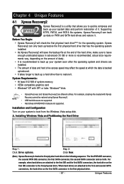
... created with SP1 or later, Windows® Vista • Xpress Recovery and Xpress Recovery2 are installed. • The amount of data and hard drive access speed may affect the speed at the end of data). • It is recommended to back up your system to the first IDE and... file at which the data is backed up/restored. • It takes longer to back up a hard drive than to restore it. Installing Windows Vista and Partitioning the Hard Drive Step 1: Click Drive options. System Requirements: • At least 512 MB of system memory • VESA compatible graphics card &#...
... created with SP1 or later, Windows® Vista • Xpress Recovery and Xpress Recovery2 are installed. • The amount of data and hard drive access speed may affect the speed at the end of data). • It is recommended to back up your system to the first IDE and... file at which the data is backed up/restored. • It takes longer to back up a hard drive than to restore it. Installing Windows Vista and Partitioning the Hard Drive Step 1: Click Drive options. System Requirements: • At least 512 MB of system memory • VESA compatible graphics card &#...
Manual
Page 58
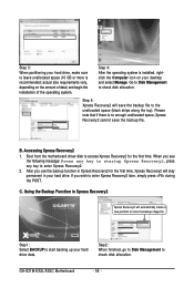
...enough unallocated space, Xpress Recovery2 cannot save the backup file to store the backup image file. GA-G31M-ES2L/ES2C Motherboard - 58 - actual size requirements vary, depending on your hard drive. Step 5: Xpress Recovery2 will save the backup file. If you use the backup function in... Recovery2 Xpress Recovery2 will stay permanent in Xpress Recovery2 for the first time. Step 1: Select BACKUP to start backing up your hard drive, make sure to enter Xpress Recovery2 later, simply press during the POST. Boot from the motherboard driver disk to enter Xpress Recovery2....
...enough unallocated space, Xpress Recovery2 cannot save the backup file to store the backup image file. GA-G31M-ES2L/ES2C Motherboard - 58 - actual size requirements vary, depending on your hard drive. Step 5: Xpress Recovery2 will save the backup file. If you use the backup function in... Recovery2 Xpress Recovery2 will stay permanent in Xpress Recovery2 for the first time. Step 1: Select BACKUP to start backing up your hard drive, make sure to enter Xpress Recovery2 later, simply press during the POST. Boot from the motherboard driver disk to enter Xpress Recovery2....
Manual
Page 59
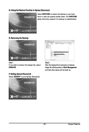
F. Step 2: After the backup file is removed, no backup image file will be present in case the system breaks down. Unique Features Exiting Xpress Recovery2 Select REBOOT to remove the backup file, select REMOVE. E. Removing the Backup Step 1: If you wish to exit Xpress Recovery2. D. Using the Restore Function in Xpress Recovery2 Select RESTORE to restore the backup to your hard drive in Disk Management and hard drive space will not be freed up. - 59 - The RESTORE option will be present if no backup is created before.
F. Step 2: After the backup file is removed, no backup image file will be present in case the system breaks down. Unique Features Exiting Xpress Recovery2 Select REBOOT to remove the backup file, select REMOVE. E. Removing the Backup Step 1: If you wish to exit Xpress Recovery2. D. Using the Restore Function in Xpress Recovery2 Select RESTORE to restore the backup to your hard drive in Disk Management and hard drive space will not be freed up. - 59 - The RESTORE option will be present if no backup is created before.


