Manual
Page 1
GA-G31-S3L LGA775 socket motherboard for Intel® CoreTM processor family/ Intel® Pentium® processor family/Intel® Celeron® processor family User's Manual Rev. 1102 12ME-G31S3L-1102R
GA-G31-S3L LGA775 socket motherboard for Intel® CoreTM processor family/ Intel® Pentium® processor family/Intel® Celeron® processor family User's Manual Rev. 1102 12ME-G31S3L-1102R
Manual
Page 2
Motherboard GA-G31-S3L Nov. 23, 2007 Motherboard GA-G31-S3L Nov. 23, 2007
Motherboard GA-G31-S3L Nov. 23, 2007 Motherboard GA-G31-S3L Nov. 23, 2007

Manual
Page 3
...2008 GIGA-BYTE TECHNOLOGY CO., LTD. All rights reserved. by copyright laws and is designated by GIGABYTE without GIGABYTE's prior written permission. For example, "REV: 1.0" means the revision of GIGABYTE branded motherboards. Documentation Classifications In order to assist in any form or by any means without ...prior notice. Example: is the property of GIGABYTE. Changes to use of this product, GIGABYTE provides the following types of documentations: „ For quick set-up of this : "REV: X.X." No part...
...2008 GIGA-BYTE TECHNOLOGY CO., LTD. All rights reserved. by copyright laws and is designated by GIGABYTE without GIGABYTE's prior written permission. For example, "REV: 1.0" means the revision of GIGABYTE branded motherboards. Documentation Classifications In order to assist in any form or by any means without ...prior notice. Example: is the property of GIGABYTE. Changes to use of this product, GIGABYTE provides the following types of documentations: „ For quick set-up of this : "REV: X.X." No part...
Manual
Page 4
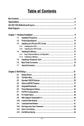
Table of Contents Box Contents ...6 OptionalItems...6 GA-G31-S3L Motherboard Layout 7 Block Diagram...8 Chapter 1 Hardware Installation 9 1-1 Installation Precautions 9 1-2 Product Specifications 10 1-3 Installing the CPU and CPU Cooler 13 1-3-1 Installing the CPU 13 1-3-2 Installing the ...
Table of Contents Box Contents ...6 OptionalItems...6 GA-G31-S3L Motherboard Layout 7 Block Diagram...8 Chapter 1 Hardware Installation 9 1-1 Installation Precautions 9 1-2 Product Specifications 10 1-3 Installing the CPU and CPU Cooler 13 1-3-1 Installing the CPU 13 1-3-2 Installing the ...
Manual
Page 5
Chapter 3 Drivers Installation 55 3-1 Installing Chipset Drivers 55 3-2 Software Applications 56 3-3 Driver CD Information 56 3-4 Hardware Information 57 3-5 Contact Us ...57 Chapter 4 Unique Features 59 4-1 Xpress Recovery2 59 4-2 BIOS Update Utilities 64 4-2-1 Updating the BIOS with the Q-Flash Utility 64 4-2-2 Updating the BIOS with the @BIOS Utility 67 4-3 EasyTune 5 Pro 69 4-4 Windows Vista ReadyBoost 70 Chapter 5 Appendix ...71 5-1 Configuring Audio Input and Output 71 5-1-1 Configuring 2/4/5.1/7.1-Channel Audio 71 5-1-2 Installing the S/PDIF In Cable (Optional 73 5-1-3 ...
Chapter 3 Drivers Installation 55 3-1 Installing Chipset Drivers 55 3-2 Software Applications 56 3-3 Driver CD Information 56 3-4 Hardware Information 57 3-5 Contact Us ...57 Chapter 4 Unique Features 59 4-1 Xpress Recovery2 59 4-2 BIOS Update Utilities 64 4-2-1 Updating the BIOS with the Q-Flash Utility 64 4-2-2 Updating the BIOS with the @BIOS Utility 67 4-3 EasyTune 5 Pro 69 4-4 Windows Vista ReadyBoost 70 Chapter 5 Appendix ...71 5-1 Configuring Audio Input and Output 71 5-1-1 Configuring 2/4/5.1/7.1-Channel Audio 71 5-1-2 Installing the S/PDIF In Cable (Optional 73 5-1-3 ...
Manual
Page 6
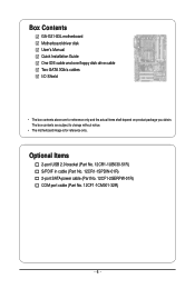
... SATA power cable (Part No. 12CF1-2SERPW-01R) COM port cable (Part No. 12CF1-1CM001-32R) - 6 - The box contents are for reference only. Box Contents GA-G31-S3L motherboard Motherboard driver disk User's Manual Quick Installation Guide One IDE cable and one floppy disk drive cable Two SATA 3Gb/s cables I/O Shield • The...
... SATA power cable (Part No. 12CF1-2SERPW-01R) COM port cable (Part No. 12CF1-1CM001-32R) - 6 - The box contents are for reference only. Box Contents GA-G31-S3L motherboard Motherboard driver disk User's Manual Quick Installation Guide One IDE cable and one floppy disk drive cable Two SATA 3Gb/s cables I/O Shield • The...
Manual
Page 7
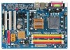
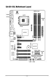
GA-G31-S3L Motherboard Layout KB_MS COAXIAL OPTICAL ATX_12V LGA775 CPU_FAN PWR_FAN VGA LPT GA-G31-S3L USB USB LAN F_AUDIO Intel® G31 AUDIO SYS_FAN1 PCIE_3 ATX DDRII1 CD_IN PCIE_16 DDRII2 DDRII3 DDRII4 RTL8111B PCIE_1 CLR_CMOS SPDIF_O CODEC SPDIF_I PCIE_2 PCI1 PCI2 IT8718 PCI3 CI COMA Intel® ICH7 BAT SATAII0 SATAII2 SYS_FAN2 BIOS SATAII1 SATAII3 IDE1 PWR_LED F_PANEL FDD F_USB1 F_USB2 - 7 -
GA-G31-S3L Motherboard Layout KB_MS COAXIAL OPTICAL ATX_12V LGA775 CPU_FAN PWR_FAN VGA LPT GA-G31-S3L USB USB LAN F_AUDIO Intel® G31 AUDIO SYS_FAN1 PCIE_3 ATX DDRII1 CD_IN PCIE_16 DDRII2 DDRII3 DDRII4 RTL8111B PCIE_1 CLR_CMOS SPDIF_O CODEC SPDIF_I PCIE_2 PCI1 PCI2 IT8718 PCI3 CI COMA Intel® ICH7 BAT SATAII0 SATAII2 SYS_FAN2 BIOS SATAII1 SATAII3 IDE1 PWR_LED F_PANEL FDD F_USB1 F_USB2 - 7 -

Manual
Page 8
Block Diagram PCIe CLK (100 MHz) D-Sub PCI Express Bus PCI Express x16 LAN RJ45 RTL 8111B x1 3 PCI Express x1 x 1 x 1 x 1 PCIe CLK (100 MHz) PCI Bus LGA775 Processor CPU CLK+/(333/266/200 MHz) Host Interface DDR2 1066/800/667 MHz Intel® G31 Dual Channel Memory GMCH CLK (333/266/200 MHz) Intel® ICH7 CODEC BIOS ATA-100/66/33 IDE Channel 4 SATA 3Gb/s 8 USB Ports IT8718 Floppy LPT Port COM Port PS/2 KB/Mouse Surround Speaker Out Center/Subwoofer Speaker Out Side Speaker Out MIC Line-Out Line-In SPDIF In SPDIF Out 3 PCI PCI CLK (33 MHz) - 8 -
Block Diagram PCIe CLK (100 MHz) D-Sub PCI Express Bus PCI Express x16 LAN RJ45 RTL 8111B x1 3 PCI Express x1 x 1 x 1 x 1 PCIe CLK (100 MHz) PCI Bus LGA775 Processor CPU CLK+/(333/266/200 MHz) Host Interface DDR2 1066/800/667 MHz Intel® G31 Dual Channel Memory GMCH CLK (333/266/200 MHz) Intel® ICH7 CODEC BIOS ATA-100/66/33 IDE Channel 4 SATA 3Gb/s 8 USB Ports IT8718 Floppy LPT Port COM Port PS/2 KB/Mouse Surround Speaker Out Center/Subwoofer Speaker Out Side Speaker Out MIC Line-Out Line-In SPDIF In SPDIF Out 3 PCI PCI CLK (33 MHz) - 8 -
Manual
Page 9
Chapter 1 Hardware Installation 1-1 Installation Precautions The motherboard contains numerous delicate electronic circuits and components which can lead to damage to system components as well as a motherboard, CPU or memory. Hardware Installation Prior to installation, carefully read the user's manual and follow these procedures: • Prior to installation, do not remove or break motherboard S/N (Serial Number) sticker or warranty sticker provided by unplugging the power cord from the motherboard, make sure the power supply has been turned off. • Before turning on the ...
Chapter 1 Hardware Installation 1-1 Installation Precautions The motherboard contains numerous delicate electronic circuits and components which can lead to damage to system components as well as a motherboard, CPU or memory. Hardware Installation Prior to installation, carefully read the user's manual and follow these procedures: • Prior to installation, do not remove or break motherboard S/N (Serial Number) sticker or warranty sticker provided by unplugging the power cord from the motherboard, make sure the power supply has been turned off. • Before turning on the ...
Manual
Page 10
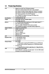
... Edition/Intel® Pentium® 4 processor/ Intel® Celeron® processor in the LGA 775 package (Go to GIGABYTE's website for the latest CPU support list.) Š L2 cache varies with CPU Š 1333/1066/800 MHz FSB Š...memory (Note 1) Š Dual channel memory architecture Š Support for DDR2 1066/800/667 MHz memory modules (Go to GIGABYTE's website for the latest memory support list.) Š Integrated in the North Bridge Š Realtek ALC888 codec Š High...(4 on the back panel, 4 via the USB brackets connected to the internal USB headers) GA-G31-S3L Motherboard - 10 -
... Edition/Intel® Pentium® 4 processor/ Intel® Celeron® processor in the LGA 775 package (Go to GIGABYTE's website for the latest CPU support list.) Š L2 cache varies with CPU Š 1333/1066/800 MHz FSB Š...memory (Note 1) Š Dual channel memory architecture Š Support for DDR2 1066/800/667 MHz memory modules (Go to GIGABYTE's website for the latest memory support list.) Š Integrated in the North Bridge Š Realtek ALC888 codec Š High...(4 on the back panel, 4 via the USB brackets connected to the internal USB headers) GA-G31-S3L Motherboard - 10 -
Manual
Page 11
Hardware Installation Internal Connectors Š 1 x 24-pin ATX main power connector Š 1 x 4-pin ATX 12V power connector Š 1 x floppy disk drive connector Š 1 x IDE connector Š 4 x SATA 3Gb/s connectors Š 1 x CPU fan header Š 2 x system fan headers Š 1 x power fan header Š 1 x front panel header Š 1 x front panel audio header Š 1 x CD In connector Š 1 x S/PDIF In header Š 1 x S/PDIF Out header Š 1 x serial port header Š 2 x USB 2.0/1.1 headers Š 1 x chassis intrusion header Š 1 x power LED header...
Hardware Installation Internal Connectors Š 1 x 24-pin ATX main power connector Š 1 x 4-pin ATX 12V power connector Š 1 x floppy disk drive connector Š 1 x IDE connector Š 4 x SATA 3Gb/s connectors Š 1 x CPU fan header Š 2 x system fan headers Š 1 x power fan header Š 1 x front panel header Š 1 x front panel audio header Š 1 x CD In connector Š 1 x S/PDIF In header Š 1 x S/PDIF Out header Š 1 x serial port header Š 2 x USB 2.0/1.1 headers Š 1 x chassis intrusion header Š 1 x power LED header...
Manual
Page 12
GA-G31-S3L Motherboard - 12 - For example, 4 GB of memory is reserved for system usage and therefore the actual memory size is less than the stated amount. Unique ...
GA-G31-S3L Motherboard - 12 - For example, 4 GB of memory is reserved for system usage and therefore the actual memory size is less than the stated amount. Unique ...
Manual
Page 13
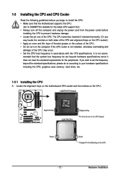
... alignment keys on the motherboard CPU socket and the notches on the CPU - 13 - Hardware Installation mended that the motherboard supports the CPU. (Go to GIGABYTE's website for the peripherals. If you may occur. • Set the CPU host frequency in accordance with the CPU specifications.
... alignment keys on the motherboard CPU socket and the notches on the CPU - 13 - Hardware Installation mended that the motherboard supports the CPU. (Go to GIGABYTE's website for the peripherals. If you may occur. • Set the CPU host frequency in accordance with the CPU specifications.
Manual
Page 14
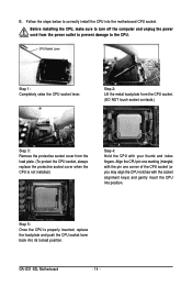
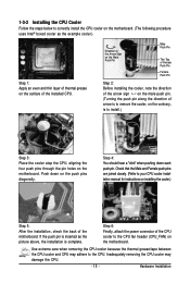
CPU Socket Lever Step 1: Completely raise the CPU socket lever. GA-G31-S3L Motherboard - 14 - Step 2: Lift the metal load plate from the CPU socket. (DO NOT touch socket contacts.) Step 3: Remove the protective socket cover from the ...
CPU Socket Lever Step 1: Completely raise the CPU socket lever. GA-G31-S3L Motherboard - 14 - Step 2: Lift the metal load plate from the CPU socket. (DO NOT touch socket contacts.) Step 3: Remove the protective socket cover from the ...
Manual
Page 15
Check that the Male and Female push pins are joined closely. (Refer to the CPU fan header (CPU_FAN) on the motherboard. Step 6: Finally, attach the power connector of the CPU cooler to your CPU cooler installation manual for instructions on installing the cooler.) Step 5: After the installation, check the back of the motherboard. Push down each push pin. Inadequately removing the CPU cooler may adhere to install.) Step 3: Place the cooler atop the CPU, aligning the four push pins through the pin holes on the motherboard. Direction of the Arrow Sign on the Male Push Pin ...
Check that the Male and Female push pins are joined closely. (Refer to the CPU fan header (CPU_FAN) on the motherboard. Step 6: Finally, attach the power connector of the CPU cooler to your CPU cooler installation manual for instructions on installing the cooler.) Step 5: After the installation, check the back of the motherboard. Push down each push pin. Inadequately removing the CPU cooler may adhere to install.) Step 3: Place the cooler atop the CPU, aligning the four push pins through the pin holes on the motherboard. Direction of the Arrow Sign on the Male Push Pin ...
Manual
Page 16
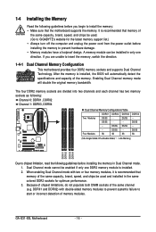
... be used . (Go to GIGABYTE's website for optimum performance. 3. Enabling Dual Channel memory mode will automatically detect the specifications and capacity of the same capacity, brand, speed, and chips be enabled if only one direction. Because of chipset limitations, do not populate both DIMM sockets of memory modules. GA-G31-S3L Motherboard - 16 - After...
... be used . (Go to GIGABYTE's website for optimum performance. 3. Enabling Dual Channel memory mode will automatically detect the specifications and capacity of the same capacity, brand, speed, and chips be enabled if only one direction. Because of chipset limitations, do not populate both DIMM sockets of memory modules. GA-G31-S3L Motherboard - 16 - After...
Manual
Page 17
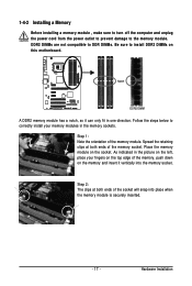
As indicated in the picture on the memory and insert it can only fit in the memory sockets. Follow the steps below to correctly install your fingers on the top edge of the memory socket. Hardware Installation Place the memory module on this motherboard. Step 1: Note the orientation of the socket will snap into the memory socket. Notch DDR2 DIMM A DDR2 memory module has a notch, so it vertically into place when the memory module is securely inserted. - 17 - Step 2: The clips at both ends of the memory module. 1-4-2 Installing a Memory Before installing a memory ...
As indicated in the picture on the memory and insert it can only fit in the memory sockets. Follow the steps below to correctly install your fingers on the top edge of the memory socket. Hardware Installation Place the memory module on this motherboard. Step 1: Note the orientation of the socket will snap into the memory socket. Notch DDR2 DIMM A DDR2 memory module has a notch, so it vertically into place when the memory module is securely inserted. - 17 - Step 2: The clips at both ends of the memory module. 1-4-2 Installing a Memory Before installing a memory ...
Manual
Page 18
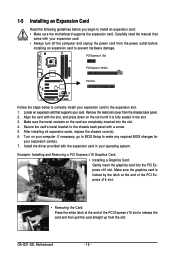
... expansion cards, replace the chassis cover(s). 6. If necessary, go to BIOS Setup to make any required BIOS changes for your expansion card in your computer. GA-G31-S3L Motherboard - 18 - Align the card with the expansion card in the expansion slot. 1. Secure the card's metal bracket to the chassis back panel with your...
... expansion cards, replace the chassis cover(s). 6. If necessary, go to BIOS Setup to make any required BIOS changes for your expansion card in your computer. GA-G31-S3L Motherboard - 18 - Align the card with the expansion card in the expansion slot. 1. Secure the card's metal bracket to the chassis back panel with your...
Manual
Page 19
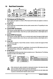
Parallel Port Use the parallel port to an external audio system that supports digital coaxial audio. Optical S/PDIF Out Connector This connector provides digital audio out to connect devices such as an USB keyboard/mouse, USB printer, USB flash drive and etc. Do not rock it straight out from the motherboard. • When removing the cable, pull it side to side to this port for USB devices such as a printer, scanner and etc. D-Sub Port The D-Sub port supports a 15-pin D-Sub connector. The following describes the states of the LAN port LEDs. Connection/ Speed LED ...
Parallel Port Use the parallel port to an external audio system that supports digital coaxial audio. Optical S/PDIF Out Connector This connector provides digital audio out to connect devices such as an USB keyboard/mouse, USB printer, USB flash drive and etc. Do not rock it straight out from the motherboard. • When removing the cable, pull it side to side to this port for USB devices such as a printer, scanner and etc. D-Sub Port The D-Sub port supports a 15-pin D-Sub connector. The following describes the states of the LAN port LEDs. Connection/ Speed LED ...
Manual
Page 20
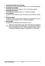
... rear speakers in jack ( ). In addition to the default speakers settings, the ~ audio jacks can be connected to the default Mic in a 4/5.1/7.1-channel audio configuration. GA-G31-S3L Motherboard - 20 - Microphones must be reconfigured to perform different functions via the audio software. Line Out Jack (Green) The default line out jack. Only microphones...
... rear speakers in jack ( ). In addition to the default speakers settings, the ~ audio jacks can be connected to the default Mic in a 4/5.1/7.1-channel audio configuration. GA-G31-S3L Motherboard - 20 - Microphones must be reconfigured to perform different functions via the audio software. Line Out Jack (Green) The default line out jack. Only microphones...