
Manual
Page 3
...designated by GIGA-BYTE TECHNOLOGY CO., LTD as the exclu- For product-related information, check on our website at: http://www.gigabyte.com.tw Identifying Your Motherboard Revision The revision number on our website. sive global distributor of the product, read the Quick ...features, read or download the information on/from the Support\Motherboard\Technology Guide page on your motherboard revision before updating motherboard BIOS, drivers, or when looking for technical information. Documentation Classifications In order to the specifications and features in any means ...
...designated by GIGA-BYTE TECHNOLOGY CO., LTD as the exclu- For product-related information, check on our website at: http://www.gigabyte.com.tw Identifying Your Motherboard Revision The revision number on our website. sive global distributor of the product, read the Quick ...features, read or download the information on/from the Support\Motherboard\Technology Guide page on your motherboard revision before updating motherboard BIOS, drivers, or when looking for technical information. Documentation Classifications In order to the specifications and features in any means ...
Manual
Page 4
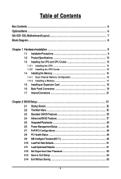
Table of Contents Box Contents ...6 OptionalItems...6 GA-G31-S3L Motherboard Layout 7 Block Diagram...8 Chapter 1 Hardware Installation 9 1-1 Installation Precautions 9 1-2 Product Specifications 10 1-3 Installing the CPU and CPU Cooler 13 ... Memory 17 1-5 Installing an Expansion Card 18 1-6 Back Panel Connectors 19 1-7 Internal Connectors 21 Chapter 2 BIOS Setup 31 2-1 Startup Screen 32 2-2 The Main Menu 33 2-3 Standard CMOS Features 35 2-4 Advanced BIOS Features 37 2-5 IntegratedPeripherals 40 2-6 Power Management Setup 43 2-7 PnP/PCI Configurations 45 2-8 PC Health Status 46...
Table of Contents Box Contents ...6 OptionalItems...6 GA-G31-S3L Motherboard Layout 7 Block Diagram...8 Chapter 1 Hardware Installation 9 1-1 Installation Precautions 9 1-2 Product Specifications 10 1-3 Installing the CPU and CPU Cooler 13 ... Memory 17 1-5 Installing an Expansion Card 18 1-6 Back Panel Connectors 19 1-7 Internal Connectors 21 Chapter 2 BIOS Setup 31 2-1 Startup Screen 32 2-2 The Main Menu 33 2-3 Standard CMOS Features 35 2-4 Advanced BIOS Features 37 2-5 IntegratedPeripherals 40 2-6 Power Management Setup 43 2-7 PnP/PCI Configurations 45 2-8 PC Health Status 46...
Manual
Page 5
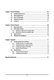
... 56 3-3 Driver CD Information 56 3-4 Hardware Information 57 3-5 Contact Us ...57 Chapter 4 Unique Features 59 4-1 Xpress Recovery2 59 4-2 BIOS Update Utilities 64 4-2-1 Updating the BIOS with the Q-Flash Utility 64 4-2-2 Updating the BIOS with the @BIOS Utility 67 4-3 EasyTune 5 Pro 69 4-4 Windows Vista ReadyBoost 70 Chapter 5 Appendix ...71 5-1 Configuring Audio Input and Output 71...
... 56 3-3 Driver CD Information 56 3-4 Hardware Information 57 3-5 Contact Us ...57 Chapter 4 Unique Features 59 4-1 Xpress Recovery2 59 4-2 BIOS Update Utilities 64 4-2-1 Updating the BIOS with the Q-Flash Utility 64 4-2-2 Updating the BIOS with the @BIOS Utility 67 4-3 EasyTune 5 Pro 69 4-4 Windows Vista ReadyBoost 70 Chapter 5 Appendix ...71 5-1 Configuring Audio Input and Output 71...
Manual
Page 7
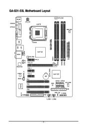
GA-G31-S3L Motherboard Layout KB_MS COAXIAL OPTICAL ATX_12V LGA775 CPU_FAN PWR_FAN VGA LPT GA-G31-S3L USB USB LAN F_AUDIO Intel® G31 AUDIO SYS_FAN1 PCIE_3 ATX DDRII1 CD_IN PCIE_16 DDRII2 DDRII3 DDRII4 RTL8111B PCIE_1 CLR_CMOS SPDIF_O CODEC SPDIF_I PCIE_2 PCI1 PCI2 IT8718 PCI3 CI COMA Intel® ICH7 BAT SATAII0 SATAII2 SYS_FAN2 BIOS SATAII1 SATAII3 IDE1 PWR_LED F_PANEL FDD F_USB1 F_USB2 - 7 -
GA-G31-S3L Motherboard Layout KB_MS COAXIAL OPTICAL ATX_12V LGA775 CPU_FAN PWR_FAN VGA LPT GA-G31-S3L USB USB LAN F_AUDIO Intel® G31 AUDIO SYS_FAN1 PCIE_3 ATX DDRII1 CD_IN PCIE_16 DDRII2 DDRII3 DDRII4 RTL8111B PCIE_1 CLR_CMOS SPDIF_O CODEC SPDIF_I PCIE_2 PCI1 PCI2 IT8718 PCI3 CI COMA Intel® ICH7 BAT SATAII0 SATAII2 SYS_FAN2 BIOS SATAII1 SATAII3 IDE1 PWR_LED F_PANEL FDD F_USB1 F_USB2 - 7 -

Manual
Page 8
Block Diagram PCIe CLK (100 MHz) D-Sub PCI Express Bus PCI Express x16 LAN RJ45 RTL 8111B x1 3 PCI Express x1 x 1 x 1 x 1 PCIe CLK (100 MHz) PCI Bus LGA775 Processor CPU CLK+/(333/266/200 MHz) Host Interface DDR2 1066/800/667 MHz Intel® G31 Dual Channel Memory GMCH CLK (333/266/200 MHz) Intel® ICH7 CODEC BIOS ATA-100/66/33 IDE Channel 4 SATA 3Gb/s 8 USB Ports IT8718 Floppy LPT Port COM Port PS/2 KB/Mouse Surround Speaker Out Center/Subwoofer Speaker Out Side Speaker Out MIC Line-Out Line-In SPDIF In SPDIF Out 3 PCI PCI CLK (33 MHz) - 8 -
Block Diagram PCIe CLK (100 MHz) D-Sub PCI Express Bus PCI Express x16 LAN RJ45 RTL 8111B x1 3 PCI Express x1 x 1 x 1 x 1 PCIe CLK (100 MHz) PCI Bus LGA775 Processor CPU CLK+/(333/266/200 MHz) Host Interface DDR2 1066/800/667 MHz Intel® G31 Dual Channel Memory GMCH CLK (333/266/200 MHz) Intel® ICH7 CODEC BIOS ATA-100/66/33 IDE Channel 4 SATA 3Gb/s 8 USB Ports IT8718 Floppy LPT Port COM Port PS/2 KB/Mouse Surround Speaker Out Center/Subwoofer Speaker Out Side Speaker Out MIC Line-Out Line-In SPDIF In SPDIF Out 3 PCI PCI CLK (33 MHz) - 8 -
Manual
Page 11
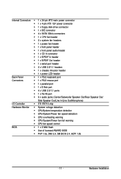
... temperature detection Š CPU/System/Power fan speed detection Š CPU overheating warning Š CPU/System/Power fan fail warning Š CPU fan speed control BIOS Š 1 x 8 Mbit flash Š Use of licensed AWARD...
... temperature detection Š CPU/System/Power fan speed detection Š CPU overheating warning Š CPU/System/Power fan fail warning Š CPU fan speed control BIOS Š 1 x 8 Mbit flash Š Use of licensed AWARD...
Manual
Page 12
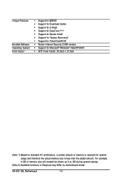
For example, 4 GB of memory is less than the stated amount. GA-G31-S3L Motherboard - 12 - Unique Features Bundled Software Operating System Form Factor Š Support for @BIOS Š Support for Download Center Š Support for Q-Flash Š Support for EasyTune (Note 2) Š Support for ...Xpress Install Š Support for Xpress Recovery2 Š Support for Virtual Dual BIOS Š Norton Internet Security (OEM version) Š Support for system usage and therefore the actual memory size is reserved for Microsoft®...
For example, 4 GB of memory is less than the stated amount. GA-G31-S3L Motherboard - 12 - Unique Features Bundled Software Operating System Form Factor Š Support for @BIOS Š Support for Download Center Š Support for Q-Flash Š Support for EasyTune (Note 2) Š Support for ...Xpress Install Š Support for Xpress Recovery2 Š Support for Virtual Dual BIOS Š Norton Internet Security (OEM version) Š Support for system usage and therefore the actual memory size is reserved for Microsoft®...
Manual
Page 16
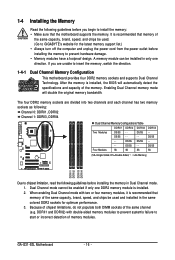
...speed, and chips be used . (Go to GIGABYTE's website for optimum performance. 3. SS DDRII4 - SS DDRII2 - - When enabling Dual Channel mode with double-sided memory modules to prevent system's failure to start or incorrect detection of memory modules. GA-G31-S3L Motherboard - 16 - A memory module can ...unplug the power cord from the power outlet before installing the memory in only one DDR2 memory module is installed, the BIOS will double the original memory bandwidth. 1-4 Installing the Memory Read the following guidelines before you are divided into two channels...
...speed, and chips be used . (Go to GIGABYTE's website for optimum performance. 3. SS DDRII4 - SS DDRII2 - - When enabling Dual Channel mode with double-sided memory modules to prevent system's failure to start or incorrect detection of memory modules. GA-G31-S3L Motherboard - 16 - A memory module can ...unplug the power cord from the power outlet before installing the memory in only one DDR2 memory module is installed, the BIOS will double the original memory bandwidth. 1-4 Installing the Memory Read the following guidelines before you are divided into two channels...
Manual
Page 18
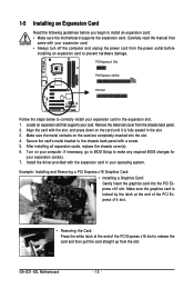
...'s metal bracket to the chassis back panel with the slot, and press down on your expansion card(s). 7. If necessary, go to BIOS Setup to make any required BIOS changes for your computer. GA-G31-S3L Motherboard - 18 - Carefully read the manual that supports your operating system. Align the card with a screw. 5. Remove the metal slot...
...'s metal bracket to the chassis back panel with the slot, and press down on your expansion card(s). 7. If necessary, go to BIOS Setup to make any required BIOS changes for your computer. GA-G31-S3L Motherboard - 18 - Carefully read the manual that supports your operating system. Align the card with a screw. 5. Remove the metal slot...
Manual
Page 26
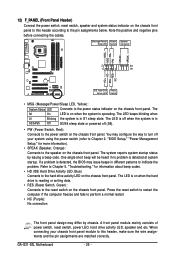
...panel. PW+ PWSPEAK+ SPEAK- 2 20 1 19 HD+ HD- The LED is off when the system is detected, the BIOS may configure the way to turn off (S5). • PW (Power Switch, Red): Connects to the power switch on the...to this header according to the pin assignments below. When connecting your system using the power switch (refer to Chapter 2, "BIOS Setup," "Power Management Setup," for information about beep codes. • HD (IDE Hard Drive Activity LED, Blue) ... of power switch, reset switch, power LED, hard drive activity LED, speaker and etc. GA-G31-S3L Motherboard - 26 -
...panel. PW+ PWSPEAK+ SPEAK- 2 20 1 19 HD+ HD- The LED is off when the system is detected, the BIOS may configure the way to turn off (S5). • PW (Power Switch, Red): Connects to the power switch on the...to this header according to the pin assignments below. When connecting your system using the power switch (refer to Chapter 2, "BIOS Setup," "Power Management Setup," for information about beep codes. • HD (IDE Hard Drive Activity LED, Blue) ... of power switch, reset switch, power LED, hard drive activity LED, speaker and etc. GA-G31-S3L Motherboard - 26 -
Manual
Page 29
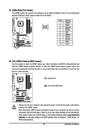
... may cause damage to the motherboard. • After system restart, go to BIOS Setup to load factory defaults (select Load Optimized Defaults) or manually configure the BIOS settings (refer to Chapter 2, "BIOS Setup," for a few seconds. Hardware Installation date information and BIOS configurations) and reset the CMOS values to clear the CMOS values (e.g. 17... power cord from the jumper. Open: Normal Short: Clear CMOS Values • Always turn off your computer, be sure to touch the two pins for BIOS configurations). - 29 -
... may cause damage to the motherboard. • After system restart, go to BIOS Setup to load factory defaults (select Load Optimized Defaults) or manually configure the BIOS settings (refer to Chapter 2, "BIOS Setup," for a few seconds. Hardware Installation date information and BIOS configurations) and reset the CMOS values to clear the CMOS values (e.g. 17... power cord from the jumper. Open: Normal Short: Clear CMOS Values • Always turn off your computer, be sure to touch the two pins for BIOS configurations). - 29 -

Manual
Page 30
... remove the battery from the battery holder and wait for one . Plug in the CMOS when the computer is replaced with local environmental regulations. GA-G31-S3L Motherboard - 30 - 19) CI (Chassis Intrusion Header) This motherboard provides a chassis detection feature that detects if the chassis cover has been ... the positive side (+) and the negative side (-) of purchase or local dealer if you are not able to keep the values (such as BIOS configurations, date, and time information) in the power cord and restart your computer. • Always turn off your computer and unplug the power...
... remove the battery from the battery holder and wait for one . Plug in the CMOS when the computer is replaced with local environmental regulations. GA-G31-S3L Motherboard - 30 - 19) CI (Chassis Intrusion Header) This motherboard provides a chassis detection feature that detects if the chassis cover has been ... the positive side (+) and the negative side (-) of purchase or local dealer if you are not able to keep the values (such as BIOS configurations, date, and time information) in the power cord and restart your computer. • Always turn off your computer and unplug the power...

Manual
Page 31
... boot. Refer to prevent system instability or other unexpected results. To upgrade the BIOS, use either the GIGABYTE Q-Flash or @BIOS utility. • Q-Flash allows the user to quickly and easily upgrade or back up BIOS without entering the operating system. • @BIOS is turned off, the battery on the motherboard. Inadequately altering the settings...
... boot. Refer to prevent system instability or other unexpected results. To upgrade the BIOS, use either the GIGABYTE Q-Flash or @BIOS utility. • Q-Flash allows the user to quickly and easily upgrade or back up BIOS without entering the operating system. • @BIOS is turned off, the battery on the motherboard. Inadequately altering the settings...
Manual
Page 32
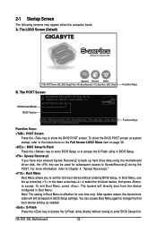
... Screen The following screens may appear when the computer boots. You can be based on page 38. : BIOS Setup/Q-Flash Press the key to enter BIOS Setup or to access the Q-Flash utility in Boot Menu. GA-G31-S3L Motherboard - 32 - The LOGO Screen (Default) :POST Screen :BIOS Setup/Q-Flash :XpressRecovery2 :Boot Menu :Qflash Function Keys B.
... Screen The following screens may appear when the computer boots. You can be based on page 38. : BIOS Setup/Q-Flash Press the key to enter BIOS Setup or to access the Q-Flash utility in Boot Menu. GA-G31-S3L Motherboard - 32 - The LOGO Screen (Default) :POST Screen :BIOS Setup/Q-Flash :XpressRecovery2 :Boot Menu :Qflash Function Keys B.

Manual
Page 33
... settings for the current submenus Access the Q-Flash utility Display system information Save all the changes and exit the BIOS Setup program Save CMOS to BIOS Load CMOS from BIOS Time, Date, Hard Disk Type... Press to exit the help screen (General Help) of function keys available for each ...& Exit Setup Exit Without Saving ESC: Quit F8: Q-Flash KLJI: Select Item F10: Save & Exit Setup F11: Save CMOS to BIOS F12: Load CMOS from BIOS Main Menu Help The onscreen description of a highlighted setup option is not stable as shown below) appears on the bottom line of the...
... settings for the current submenus Access the Q-Flash utility Display system information Save all the changes and exit the BIOS Setup program Save CMOS to BIOS Load CMOS from BIOS Time, Date, Hard Disk Type... Press to exit the help screen (General Help) of function keys available for each ...& Exit Setup Exit Without Saving ESC: Quit F8: Q-Flash KLJI: Select Item F10: Save & Exit Setup F11: Save CMOS to BIOS F12: Load CMOS from BIOS Main Menu Help The onscreen description of a highlighted setup option is not stable as shown below) appears on the bottom line of the...
Manual
Page 34
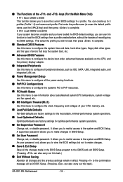
...types, floppy disk drive types, and the type of errors that stop the system boot, etc. „ Advanced BIOS Features Use this menu to configure the device boot order, advanced features available on the CPU, and the primary ... (Profile 1-8) and name each profile. A supervisor password allows you can also carry out this function to load the BIOS settings from BIOS If your CPU, memory, etc. „ Load Fail-Safe Defaults Fail-Safe defaults are factory settings for the most... and fan speed, etc. „ MB Intelligent Tweaker(M.I.T.) Use this task.) GA-G31-S3L Motherboard - 34 -
...types, floppy disk drive types, and the type of errors that stop the system boot, etc. „ Advanced BIOS Features Use this menu to configure the device boot order, advanced features available on the CPU, and the primary ... (Profile 1-8) and name each profile. A supervisor password allows you can also carry out this function to load the BIOS settings from BIOS If your CPU, memory, etc. „ Load Fail-Safe Defaults Fail-Safe defaults are factory settings for the most... and fan speed, etc. „ MB Intelligent Tweaker(M.I.T.) Use this task.) GA-G31-S3L Motherboard - 34 -
Manual
Page 35
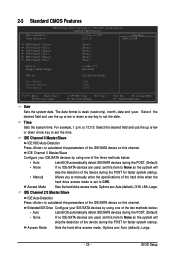
... example, 1 p.m. IDE Channel 0 Master/Slave IDE HDD Auto-Detection Press to autodetect the parameters of the two methods below : • Auto Lets BIOS automatically detect IDE/SATA devices during the POST. (Default) • None • Manual If no IDE/SATA devices are used , set this channel.... Extended IDE Drive Configure your IDE/SATA devices by using one of the IDE/SATA device on this item to CHS. BIOS Setup 2-3 Standard CMOS Features Date (mm:dd:yy) Time (hh:mm:ss) CMOS Setup Utility-Copyright (C) 1984-2007 Award Software Standard CMOS...
... example, 1 p.m. IDE Channel 0 Master/Slave IDE HDD Auto-Detection Press to autodetect the parameters of the two methods below : • Auto Lets BIOS automatically detect IDE/SATA devices during the POST. (Default) • None • Manual If no IDE/SATA devices are used , set this channel.... Extended IDE Drive Configure your IDE/SATA devices by using one of the IDE/SATA device on this item to CHS. BIOS Setup 2-3 Standard CMOS Features Date (mm:dd:yy) Time (hh:mm:ss) CMOS Setup Utility-Copyright (C) 1984-2007 Award Software Standard CMOS...
Manual
Page 36
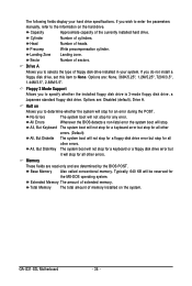
... determine whether the system will not stop for any error. All Errors Whenever the BIOS detects a non-fatal error the system boot will be reserved for an error during the POST. GA-G31-S3L Motherboard - 36 - Capacity Approximate capacity of sectors. Head Number of floppy disk ... : None, 360K/5.25", 1.2M/5.25", 720K/3.5", 1.44M/3.5", 2.88M/3.5". The following fields display your system. Options are determined by the BIOS POST. Typically, 640 KB will stop for the MS-DOS operating system. Precomp Write precompensation cylinder. If you to the information on the system...
... determine whether the system will not stop for any error. All Errors Whenever the BIOS detects a non-fatal error the system boot will be reserved for an error during the POST. GA-G31-S3L Motherboard - 36 - Capacity Approximate capacity of sectors. Head Number of floppy disk ... : None, 360K/5.25", 1.2M/5.25", 720K/3.5", 1.44M/3.5", 2.88M/3.5". The following fields display your system. Options are determined by the BIOS POST. Typically, 640 KB will stop for the MS-DOS operating system. Precomp Write precompensation cylinder. If you to the information on the system...
Manual
Page 37
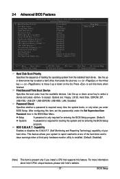
...] [Enabled] [Enabled] [Enabled] [Enabled] [PCI] Onboard VGA On-Chip Frame Buffer Size [Enable If No Ext PEG] [8MB+1~2MB for entering the BIOS Setup program. Use the up or down arrow key to select a device and press to exit this menu when finished. to issue warnings when a third... party hardware monitor utility is installed. (Default: Disabled) (Note) This item is present only if you enter BIOS Setup. Press to accept. Capability Limit CPUID Max. HDD S.M.A.R.T. This feature allows your system to move it up or down on the list....
...] [Enabled] [Enabled] [Enabled] [Enabled] [PCI] Onboard VGA On-Chip Frame Buffer Size [Enable If No Ext PEG] [8MB+1~2MB for entering the BIOS Setup program. Use the up or down arrow key to select a device and press to exit this menu when finished. to issue warnings when a third... party hardware monitor utility is installed. (Default: Disabled) (Note) This item is present only if you enter BIOS Setup. Press to accept. Capability Limit CPUID Max. HDD S.M.A.R.T. This feature allows your system to move it up or down on the list....

Manual
Page 39
On-Chip Frame Buffer Size Frame buffer size is the total amount of system memory allocated solely for GTT. - 39 - Options are: 8MB+1~2MB for GTT (default), 1MB+1~2MB for the onboard graphics controller. BIOS Setup MS-DOS, for example, will use only this memory for display.
On-Chip Frame Buffer Size Frame buffer size is the total amount of system memory allocated solely for GTT. - 39 - Options are: 8MB+1~2MB for GTT (default), 1MB+1~2MB for the onboard graphics controller. BIOS Setup MS-DOS, for example, will use only this memory for display.


