
User Manual
Page 14
...): Connects to the reset switch on the chassis front panel. The front panel design may configure NC RES+ RESHD- For information about connecting the S/PDIF digital audio cable, carefully read the manual for your system using the power switch (refer to Chapter 2, "BIOS Setup," "Power Management," ...for more information). •• HD (Hard Drive Activity LED): Connects to the hard drive activity LED on the chassis front panel. The Hard Drive Reset Activity LED Switch LED is on the chassis to...
...): Connects to the reset switch on the chassis front panel. The front panel design may configure NC RES+ RESHD- For information about connecting the S/PDIF digital audio cable, carefully read the manual for your system using the power switch (refer to Chapter 2, "BIOS Setup," "Power Management," ...for more information). •• HD (Hard Drive Activity LED): Connects to the hard drive activity LED on the chassis front panel. The Hard Drive Reset Activity LED Switch LED is on the chassis to...
User Manual
Page 16
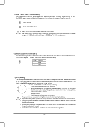
...installing the battery, note the orientation of the positive side (+) and the negative side (-) of the battery holder, making them short for BIOS configurations). 12) CI (Chassis Intrusion Header) This motherboard provides a chassis detection feature that detects if the chassis cover has been removed. ...the battery when the battery voltage drops to Chapter 2, "BIOS Setup," for 5 seconds.) 3. 11) CLR_CMOS (Clear CMOS Jumper) Use this jumper to clear the BIOS configuration and reset the CMOS values to keep the values (such as BIOS configurations, date, and time information) in the CMOS when ...
...installing the battery, note the orientation of the positive side (+) and the negative side (-) of the battery holder, making them short for BIOS configurations). 12) CI (Chassis Intrusion Header) This motherboard provides a chassis detection feature that detects if the chassis cover has been removed. ...the battery when the battery voltage drops to Chapter 2, "BIOS Setup," for 5 seconds.) 3. 11) CLR_CMOS (Clear CMOS Jumper) Use this jumper to clear the BIOS configuration and reset the CMOS values to keep the values (such as BIOS configurations, date, and time information) in the CMOS when ...
User Manual
Page 17
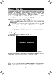
... values in system's failure to boot. Or you can use either the GIGABYTE Q-Flash or @BIOS utility. •• Q-Flash allows the user to quickly and easily upgrade or back up BIOS without entering the operating system. •• @BIOS is a Windows-based utility that you not alter the default settings (unless... menus described in the CMOS on . To upgrade the BIOS, use your mouse to select the item you do it is turned on the motherboard. If this occurs, try to clear the CMOS values and reset the board to default values. (Refer to the "Load Optimized Defaults" section in this...
... values in system's failure to boot. Or you can use either the GIGABYTE Q-Flash or @BIOS utility. •• Q-Flash allows the user to quickly and easily upgrade or back up BIOS without entering the operating system. •• @BIOS is a Windows-based utility that you not alter the default settings (unless... menus described in the CMOS on . To upgrade the BIOS, use your mouse to select the item you do it is turned on the motherboard. If this occurs, try to clear the CMOS values and reset the board to default values. (Refer to the "Load Optimized Defaults" section in this...

User Manual
Page 18
...advanced users only and we recommend you to alter the clock ratio for the installed CPU. If this occurs, clear the CMOS values and reset the board to CPU, chipset, or memory and reduce the useful life of these components. The adjustable range is from 800 MHz to 6000...: It is dependent on CPU/memory frequencies/parameters. `` Advanced Frequency Settings && CPU Clock Control Allows you to those under the same items on the BIOS version, CPU base clock, CPU frequency, memory frequency, total memory size, CPU temperature, Vcore, and memory voltage. Whether the system will work stably ...
...advanced users only and we recommend you to alter the clock ratio for the installed CPU. If this occurs, clear the CMOS values and reset the board to CPU, chipset, or memory and reduce the useful life of these components. The adjustable range is from 800 MHz to 6000...: It is dependent on CPU/memory frequencies/parameters. `` Advanced Frequency Settings && CPU Clock Control Allows you to those under the same items on the BIOS version, CPU base clock, CPU frequency, memory frequency, total memory size, CPU temperature, Vcore, and memory voltage. Whether the system will work stably ...


