
Manual
Page 4
Table of Contents Box Contents ...6 Optional Items...6 GA-EX58-UD5P/GA-EX58-UD5 Motherboard Layout 7 Block Diagram...8 Chapter 1 Hardware Installation 9 1-1 Installation Precautions 9 1-2 Product Specifications 10 1-3 Installing the CPU and CPU Cooler 13 1-3-1 ...16 1-4-2 Installing a Memory 17 1-5 Installing an Expansion Card 18 1-6 Setup of NVIDIA SLI (Scalable Link Interface)/ATI CrossFireX Configuration. 19 1-7 Installing the SATA Bracket 22 1-8 Back Panel Connectors 23 1-9 Onboard LEDs and Switches 25 1-10 Internal Connectors 27 Chapter 2 BIOS Setup 41 2-1 Startup Screen 42 2-2...
Table of Contents Box Contents ...6 Optional Items...6 GA-EX58-UD5P/GA-EX58-UD5 Motherboard Layout 7 Block Diagram...8 Chapter 1 Hardware Installation 9 1-1 Installation Precautions 9 1-2 Product Specifications 10 1-3 Installing the CPU and CPU Cooler 13 1-3-1 ...16 1-4-2 Installing a Memory 17 1-5 Installing an Expansion Card 18 1-6 Setup of NVIDIA SLI (Scalable Link Interface)/ATI CrossFireX Configuration. 19 1-7 Installing the SATA Bracket 22 1-8 Back Panel Connectors 23 1-9 Onboard LEDs and Switches 25 1-10 Internal Connectors 27 Chapter 2 BIOS Setup 41 2-1 Startup Screen 42 2-2...
Manual
Page 5
... ...88 4-7 Time Repair ...89 4-8 Teaming ...90 Chapter 5 Appendix ...91 5-1 Configuring SATA Hard Drive(s 91 5-1-1 Configuring Intel ICH10R SATA Controllers 91 5-1-2 Configuring GIGABYTE SATA2/JMB322 SATA Controller 97 5-1-3 Making a SATA RAID/AHCI Driver Diskette 99 5-1-4 Installing the SATA RAID/AHCI Driver and Operating System 101 5-1-5 Smart Backup Utility 106 5-2 Configuring AudioInput and Output... 5-3 Troubleshooting 115 5-3-1 Frequently Asked Questions 115 5-3-2 Troubleshooting Procedure 116 5-4 POST Error Code 118 5-5 Regulatory Statements 122 "*" Only for GA-EX58-UD5P. - 5 -
... ...88 4-7 Time Repair ...89 4-8 Teaming ...90 Chapter 5 Appendix ...91 5-1 Configuring SATA Hard Drive(s 91 5-1-1 Configuring Intel ICH10R SATA Controllers 91 5-1-2 Configuring GIGABYTE SATA2/JMB322 SATA Controller 97 5-1-3 Making a SATA RAID/AHCI Driver Diskette 99 5-1-4 Installing the SATA RAID/AHCI Driver and Operating System 101 5-1-5 Smart Backup Utility 106 5-2 Configuring AudioInput and Output... 5-3 Troubleshooting 115 5-3-1 Frequently Asked Questions 115 5-3-2 Troubleshooting Procedure 116 5-4 POST Error Code 118 5-5 Regulatory Statements 122 "*" Only for GA-EX58-UD5P. - 5 -

Manual
Page 6
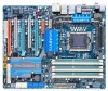
Box Contents GA-EX58-UD5P/GA-EX58-UD5 motherboard Motherboard driver disk User's Manual Quick Installation Guide One IDE cable Four SATA 3Gb/s cables One SATA bracket I/O shield 2-Way SLI bridge connector 3-Way SLI bridge connector • The box contents above are subject to change without notice. • The motherboard image ... Items Floppy disk drive cable (Part No. 12CF1-1FD001-7*R) 2-port USB 2.0 bracket (Part No. 12CR1-1UB030-5*R) 2-port IEEE 1394a bracket (Part No. 12CF1-1IE008-0*R) 2-port SATA power cable (Part No. 12CF1-2SERPW-0*R) S/PDIF in cable (Part No. 12CR1-1SPDIN-0*R) - 6 -
Box Contents GA-EX58-UD5P/GA-EX58-UD5 motherboard Motherboard driver disk User's Manual Quick Installation Guide One IDE cable Four SATA 3Gb/s cables One SATA bracket I/O shield 2-Way SLI bridge connector 3-Way SLI bridge connector • The box contents above are subject to change without notice. • The motherboard image ... Items Floppy disk drive cable (Part No. 12CF1-1FD001-7*R) 2-port USB 2.0 bracket (Part No. 12CR1-1UB030-5*R) 2-port IEEE 1394a bracket (Part No. 12CF1-1IE008-0*R) 2-port SATA power cable (Part No. 12CF1-2SERPW-0*R) S/PDIF in cable (Part No. 12CR1-1SPDIN-0*R) - 6 -
Manual
Page 8
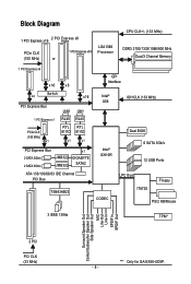
... Bus 1 PCI Express x1 PCIe CLK (100 MHz) x1 LAN2 LAN1 RJ45 RJ45 RTL RTL 8111D 8111D x1 x1 PCI Express Bus 2 SATA 3Gb/s 2 SATA 3Gb/s JMB322 JMB322 x1 GIGABYTE SATA2 ATA-133/100/66/33 IDE Channel PCI Bus TSB43AB23 QPI Interface Intel® X58 IOH CLK (133 MHz) Intel® ICH10R... Dual BIOS 6 SATA 3Gb/s 12 USB Ports CODEC LPC Bus IT8720 Floppy PS/2 KB/Mouse 3 IEEE 1394a TPM* Surround Speaker Out Center/Subwoofer Speaker Out Side Speaker Out MIC Line-Out Line-In SPDIF In SPDIF Out 2 PCI PCI CLK (33 MHz) "*" Only for GA-EX58-UD5P. - 8 -
... Bus 1 PCI Express x1 PCIe CLK (100 MHz) x1 LAN2 LAN1 RJ45 RJ45 RTL RTL 8111D 8111D x1 x1 PCI Express Bus 2 SATA 3Gb/s 2 SATA 3Gb/s JMB322 JMB322 x1 GIGABYTE SATA2 ATA-133/100/66/33 IDE Channel PCI Bus TSB43AB23 QPI Interface Intel® X58 IOH CLK (133 MHz) Intel® ICH10R... Dual BIOS 6 SATA 3Gb/s 12 USB Ports CODEC LPC Bus IT8720 Floppy PS/2 KB/Mouse 3 IEEE 1394a TPM* Surround Speaker Out Center/Subwoofer Speaker Out Side Speaker Out MIC Line-Out Line-In SPDIF In SPDIF Out 2 PCI PCI CLK (33 MHz) "*" Only for GA-EX58-UD5P. - 8 -

Manual
Page 10
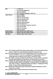
... to the internal IEEE 1394a headers) GA-EX58-UD5P/UD5 Motherboard - 10 - 1-2 Product Specifications CPU QPI Chipset Memory Audio LAN Expansion Slots Storage Interface IEEE 1394 Support for an Intel® CoreTM i7 series processor in the LGA 1366 package (Go to GIGABYTE's website for the latest CPU support ...61559; Support for S/PDIF In/Out Support for CD In 2 x Realtek 8111D chips (10/100/1000 Mbit) Support for SATA RAID 0, RAID 1 and JBOD iTE IT8720 chip: - 1 x floppy disk drive connector supporting up to 4 SA TA 3Gb/s devices (Note 4) -
... to the internal IEEE 1394a headers) GA-EX58-UD5P/UD5 Motherboard - 10 - 1-2 Product Specifications CPU QPI Chipset Memory Audio LAN Expansion Slots Storage Interface IEEE 1394 Support for an Intel® CoreTM i7 series processor in the LGA 1366 package (Go to GIGABYTE's website for the latest CPU support ...61559; Support for S/PDIF In/Out Support for CD In 2 x Realtek 8111D chips (10/100/1000 Mbit) Support for SATA RAID 0, RAID 1 and JBOD iTE IT8720 chip: - 1 x floppy disk drive connector supporting up to 4 SA TA 3Gb/s devices (Note 4) -
Manual
Page 11
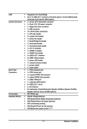
...) Internal Connectors 1 x 24-pin ATX main power connector 1 x 8-pin ATX 12V power connector 1 x floppy disk drive connector 1 x IDE connector 10 x SATA 3Gb/s connectors 1 x CPU fan header 3 x system fan headers 1 x power fan header 1 x North Bridge fan header 1 x front panel header 1 x front...
...) Internal Connectors 1 x 24-pin ATX main power connector 1 x 8-pin ATX 12V power connector 1 x floppy disk drive connector 1 x IDE connector 10 x SATA 3Gb/s connectors 1 x CPU fan header 3 x system fan headers 1 x power fan header 1 x North Bridge fan header 1 x front panel header 1 x front...
Manual
Page 12
...GSATA2_1 as a pair and GSATA2_2 and GSATA2_3 as a pair. (Refer to Chapter 2, "Integrated Peripherals" and Chapter 5, "Configuring SA TA Hard Drive(s)," for GA-EX58-UD5P. GA-EX58-UD5P/UD5 Motherboard - 12 - BIOS Unique Features Bundled Software Operating System Form Factor 2 x 8 Mbit flash Use of licensed AWARD BIOS ...with a PCI Express graphics card, the PCIEX16_2 slot will operate at up to x8 mode. (Note 4) A JMB322 chip supports two SATA 3Gb/s connectors, so the four SA TA 3Gb/s connectors are installing two PCI Express graphics cards, it in the PCIEX16_1 slot;
...GSATA2_1 as a pair and GSATA2_2 and GSATA2_3 as a pair. (Refer to Chapter 2, "Integrated Peripherals" and Chapter 5, "Configuring SA TA Hard Drive(s)," for GA-EX58-UD5P. GA-EX58-UD5P/UD5 Motherboard - 12 - BIOS Unique Features Bundled Software Operating System Form Factor 2 x 8 Mbit flash Use of licensed AWARD BIOS ...with a PCI Express graphics card, the PCIEX16_2 slot will operate at up to x8 mode. (Note 4) A JMB322 chip supports two SATA 3Gb/s connectors, so the four SA TA 3Gb/s connectors are installing two PCI Express graphics cards, it in the PCIEX16_1 slot;

Manual
Page 22
...Plug one SA TA power cable. Before connecting the SATA signal cable, make sure to the chassis back panel with a screw. Then attach the SATA power cable to the power connector on the bracket. nector on Step 5: the bracket. GA-EX58-UD5P/UD5 Motherboard - 22 - Follow the steps below to ...install the SA TA bracket: Step 1: Locate one free PCI slot and secure the SATA bracket to turn off your system and the power switch on your SATA device. the external SATA con- For SA TA device...
...Plug one SA TA power cable. Before connecting the SATA signal cable, make sure to the chassis back panel with a screw. Then attach the SATA power cable to the power connector on the bracket. nector on Step 5: the bracket. GA-EX58-UD5P/UD5 Motherboard - 22 - Follow the steps below to ...install the SA TA bracket: Step 1: Locate one free PCI slot and secure the SATA bracket to turn off your system and the power switch on your SATA device. the external SATA con- For SA TA device...

Manual
Page 31
... Definition GND TXP 3 TXN 7 SATA2_4 SATA2_2 1 SATA2_0 4 GND 5 RXN 6 RXP 7 GND Please connect the L-shaped end of the SATA 3Gb/s cable to your SATA hard drive. • A RAID 0 or RAID 1 configuration requires at least four hard drives and the total number of hard drives does not...more than two hard drives are compatible with SA TA 1.5Gb/s standard. Each SATA connector supports a single SA TA device. Hardware Installation 9) SATA2_0/1/2/3/4/5 (SATA 3Gb/s Connectors, Controlled by ICH10R) The SATA connectors conform to SA TA 3Gb/s standard and are to be used, the ...
... Definition GND TXP 3 TXN 7 SATA2_4 SATA2_2 1 SATA2_0 4 GND 5 RXN 6 RXP 7 GND Please connect the L-shaped end of the SATA 3Gb/s cable to your SATA hard drive. • A RAID 0 or RAID 1 configuration requires at least four hard drives and the total number of hard drives does not...more than two hard drives are compatible with SA TA 1.5Gb/s standard. Each SATA connector supports a single SA TA device. Hardware Installation 9) SATA2_0/1/2/3/4/5 (SATA 3Gb/s Connectors, Controlled by ICH10R) The SATA connectors conform to SA TA 3Gb/s standard and are to be used, the ...

Manual
Page 32
...connect a system power LED on when the system is in S3/S4 sleep state or powered off (S5). 1 GA-EX58-UD5P/UD5 Motherboard - 32 - Please connect the L-shaped end of the SATA 3Gb/s cable to your SATA hard drive. 11) PWR_LED (System Power LED Header) This header can be connected to either the GSATA2_0 and... LED is in S1 sleep state. The LED is off when the system is on the chassis to the G SATA2_2 and GSATA2_3 connectors. The GIGABYTE SATA2/JMB322 controller supports RAID 0, RAID 1 and JBOD. Refer to SA TA 3Gb/s standard and are compatible with SA TA 1.5Gb/s standard.
...connect a system power LED on when the system is in S3/S4 sleep state or powered off (S5). 1 GA-EX58-UD5P/UD5 Motherboard - 32 - Please connect the L-shaped end of the SATA 3Gb/s cable to your SATA hard drive. 11) PWR_LED (System Power LED Header) This header can be connected to either the GSATA2_0 and... LED is in S1 sleep state. The LED is off when the system is on the chassis to the G SATA2_2 and GSATA2_3 connectors. The GIGABYTE SATA2/JMB322 controller supports RAID 0, RAID 1 and JBOD. Refer to SA TA 3Gb/s standard and are compatible with SA TA 1.5Gb/s standard.
Manual
Page 55
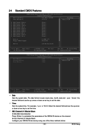
... use the up arrow or down arrow key to autodetect the parameters of the three methods below: - 55 - IDE Channel 0/1 Master/Slave Configure your IDE/SATA devices by using one of the IDE/SA TA device on this channel. The date format is 13:0:0. is week (read-only), month, date and...
... use the up arrow or down arrow key to autodetect the parameters of the three methods below: - 55 - IDE Channel 0/1 Master/Slave Configure your IDE/SATA devices by using one of the IDE/SA TA device on this channel. The date format is 13:0:0. is week (read-only), month, date and...

Manual
Page 56
... this item to None so the system will stop for all other errors. Landing Zone Landing zone. GA-EX58-UD5P/UD5 Motherboard - 56 - Access Mode Sets the hard drive access mode. The following fields display your IDE/SATA devices by the BIOS POST. Precomp Write precompensation cylinder. All, But Disk/Key The system boot...
... this item to None so the system will stop for all other errors. Landing Zone Landing zone. GA-EX58-UD5P/UD5 Motherboard - 56 - Access Mode Sets the hard drive access mode. The following fields display your IDE/SATA devices by the BIOS POST. Precomp Write precompensation cylinder. All, But Disk/Key The system boot...

Manual
Page 59
...Allows USB mouse to be shared with other device. RAID Enables RAID for the SATA controllers and configures the SATA controllers to PATA mode. (Default) AHCI Configures the SATA controllers to install operating systems that cannot be used in Native IDE mode. ... H/W 1394 Onboard H/W LAN1 Onboard H/W LAN2 Green LAN SMART LAN1 SMART LAN2 Onboard LAN1 Boot ROM Onboard LAN2 Boot ROM Onboard SATA/IDE Device Onboard SATA/IDE Ctrl Mode Smart Backup [Disabled] [Disabled] [Enabled] [Enabled] [Disabled] [Disabled] [Enabled] [Auto] [Enabled] [Enabled] ...
...Allows USB mouse to be shared with other device. RAID Enables RAID for the SATA controllers and configures the SATA controllers to PATA mode. (Default) AHCI Configures the SATA controllers to install operating systems that cannot be used in Native IDE mode. ... H/W 1394 Onboard H/W LAN1 Onboard H/W LAN2 Green LAN SMART LAN1 SMART LAN2 Onboard LAN1 Boot ROM Onboard LAN2 Boot ROM Onboard SATA/IDE Device Onboard SATA/IDE Ctrl Mode Smart Backup [Disabled] [Disabled] [Enabled] [Enabled] [Disabled] [Disabled] [Enabled] [Auto] [Enabled] [Enabled] ...

Manual
Page 61
... Chip) Enables or disables the IDE and SA TA controllers integrated in the GIGABYTE SA TA 2 chip. (Default: Enabled) Onboard SATA/IDE Ctrl Mode (GIGABYTE SATA2 Chip) Allows you have to install the SATA controller driver during the OS installation. When a Cable Problem Occurs... Note:... is activated. BIOS Setup Refer to Chapter 5, "Configuring SATA Hard Drive(s)," for how to AHCI mode. If a cable problem occurs on Part 1-2. IDE Configures the SATA controller to PATA mode. (Default) AHCI Configures the SATA controller to make a driver diskette and install the driver ...
... Chip) Enables or disables the IDE and SA TA controllers integrated in the GIGABYTE SA TA 2 chip. (Default: Enabled) Onboard SATA/IDE Ctrl Mode (GIGABYTE SATA2 Chip) Allows you have to install the SATA controller driver during the OS installation. When a Cable Problem Occurs... Note:... is activated. BIOS Setup Refer to Chapter 5, "Configuring SATA Hard Drive(s)," for how to AHCI mode. If a cable problem occurs on Part 1-2. IDE Configures the SATA controller to PATA mode. (Default) AHCI Configures the SATA controller to make a driver diskette and install the driver ...

Manual
Page 62
...the hard drive(s) connected to the GSATA2_0~3 connectors or to view the device status in the operating system. After the configuration, ensure the SATA controller driver has been installed in the operating system. Controller 0 (GSATA2 0/1)/ Controller 1 (GSATA2 2/3) CMOS Setup Utility-Copyright (C) 1984-...Select F5: Previous Values +/-/PU/PD: Value F10: Save F6: Fail-Safe Defaults ESC: Exit F1: General Help F7: Optimized Defaults GA-EX58-UD5P/UD5 Motherboard - 62 - You can install the Smart Backup utility (refer to Chapter 5, "Configuring SA TA Hard Drive(s)," to configure a ...
...the hard drive(s) connected to the GSATA2_0~3 connectors or to view the device status in the operating system. After the configuration, ensure the SATA controller driver has been installed in the operating system. Controller 0 (GSATA2 0/1)/ Controller 1 (GSATA2 2/3) CMOS Setup Utility-Copyright (C) 1984-...Select F5: Previous Values +/-/PU/PD: Value F10: Save F6: Fail-Safe Defaults ESC: Exit F1: General Help F7: Optimized Defaults GA-EX58-UD5P/UD5 Motherboard - 62 - You can install the Smart Backup utility (refer to Chapter 5, "Configuring SA TA Hard Drive(s)," to configure a ...

Manual
Page 77
..., Xpress Recovery2 can only back up/restore the first physical hard drive that allows you to quickly compress and back up data on the first SATA connector is the first physical drive. - 77 - System Requirements: • Intel® platform • At least 512 MB of it. A. When ... your system to leave enough unallocated space in the following sequence: The first PATA IDE connector, the second PATA IDE connector, the first SATA connector, the second SATA connector and so forth. For example, a backup file created with SP1 or later, Windows ® Vista • Xpress Recovery and ...
..., Xpress Recovery2 can only back up/restore the first physical hard drive that allows you to quickly compress and back up data on the first SATA connector is the first physical drive. - 77 - System Requirements: • Intel® platform • At least 512 MB of it. A. When ... your system to leave enough unallocated space in the following sequence: The first PATA IDE connector, the second PATA IDE connector, the first SATA connector, the second SATA connector and so forth. For example, a backup file created with SP1 or later, Windows ® Vista • Xpress Recovery and ...

Manual
Page 81
... the main menu. Step 3: When the update process is saved to a hard drive in RAID/AHCI mode or a hard drive attached to an independent IDE/SATA controller, use the up or down arrow key to select Update BIOS from Drive and press . • The Save Main BIOS to Drive option allows...
... the main menu. Step 3: When the update process is saved to a hard drive in RAID/AHCI mode or a hard drive attached to an independent IDE/SATA controller, use the up or down arrow key to select Update BIOS from Drive and press . • The Save Main BIOS to Drive option allows...

Manual
Page 89
..., Time Repair allows you cannot edit the contents of a shadow copy. - 89 - System Restore Choose a system restore point using the navigation bar on P ATA and SATA hard drives. Shadow copies are read-only so you to view the system data backed up and restore your system data in the Windows Vista...
..., Time Repair allows you cannot edit the contents of a shadow copy. - 89 - System Restore Choose a system restore point using the navigation bar on P ATA and SATA hard drives. Shadow copies are read-only so you to view the system data backed up and restore your system data in the Windows Vista...

Manual
Page 91
...is more than one SA TA controller on your motherboard, refer to "Chapter 1," "Hardware Installation," to identify the SA TA controller for the SATA port. (For example, on this motherboard, the SA TA2_0, SATA2_1, SATA2_2, SATA2_3, SATA2_4 and SATA2_5 ports are supported by ICH10R South ...Note 1)(Note 2) D. Configure a RAID array in BIOS Setup. Make a floppy disk containing the SA TA RAID/AHCI driver. (Note 2) E. Appendix Installing SATA hard drive(s) in your computer Attach one hard drive. • An empty formatted floppy disk. • Windows Vista/XP setup disk. • Motherboard ...
...is more than one SA TA controller on your motherboard, refer to "Chapter 1," "Hardware Installation," to identify the SA TA controller for the SATA port. (For example, on this motherboard, the SA TA2_0, SATA2_1, SATA2_2, SATA2_3, SATA2_4 and SATA2_5 ports are supported by ICH10R South ...Note 1)(Note 2) D. Configure a RAID array in BIOS Setup. Make a floppy disk containing the SA TA RAID/AHCI driver. (Note 2) E. Appendix Installing SATA hard drive(s) in your computer Attach one hard drive. • An empty formatted floppy disk. • Windows Vista/XP setup disk. • Motherboard ...

Manual
Page 92
B. If you have and the BIOS version. GA-EX58-UD5P/UD5 Motherboard - 92 - CMOS Setup Utility-Copyright (C) 1984-2008 Award Software Integrated Peripherals SATA RAID/AHCI Mode SATA Port0-3 Native Mode USB 1.0 Controller USB 2.0 Controller USB Keyboard Function USB Mouse Function USB ... 1394 Onboard H/W LAN1 Onboard H/W LAN2 Green LAN SMART LAN1 SMART LAN2 Onboard LAN1 Boot ROM Onboard LAN2 Boot ROM Onboard SATA/IDE Device Onboard SATA/IDE Ctrl Mode Smart Backup [RAID] [Disabled] [Enabled] [Enabled] [Disabled] [Disabled] [Enabled] [Auto] [Enabled] [Enabled]...
B. If you have and the BIOS version. GA-EX58-UD5P/UD5 Motherboard - 92 - CMOS Setup Utility-Copyright (C) 1984-2008 Award Software Integrated Peripherals SATA RAID/AHCI Mode SATA Port0-3 Native Mode USB 1.0 Controller USB 2.0 Controller USB Keyboard Function USB Mouse Function USB ... 1394 Onboard H/W LAN1 Onboard H/W LAN2 Green LAN SMART LAN1 SMART LAN2 Onboard LAN1 Boot ROM Onboard LAN2 Boot ROM Onboard SATA/IDE Device Onboard SATA/IDE Ctrl Mode Smart Backup [RAID] [Disabled] [Enabled] [Enabled] [Disabled] [Disabled] [Enabled] [Auto] [Enabled] [Enabled]...


