Manual
Page 1
GA-EX58-UD5P/ GA-EX58-UD5 LGA1366 socket motherboard for Intel® CoreTM i7 processor family User's Manual Rev. 1005 12ME-EX58UD5-1005R
GA-EX58-UD5P/ GA-EX58-UD5 LGA1366 socket motherboard for Intel® CoreTM i7 processor family User's Manual Rev. 1005 12ME-EX58UD5-1005R

Manual
Page 2
Motherboard GA-EX58-UD5P/GA-EX58-UD5 Oct. 31, 2008 Motherboard GA-EX58-UD5P/ GA-EX58-UD5 Oct. 31, 2008
Motherboard GA-EX58-UD5P/GA-EX58-UD5 Oct. 31, 2008 Motherboard GA-EX58-UD5P/ GA-EX58-UD5 Oct. 31, 2008
Manual
Page 3
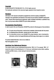
...Revision The revision number on our website. Disclaimer Information in this manual may be made by any form or by GIGABYTE without GIGABYTE's prior written permission. The trademarks mentioned in this manual is protected by copyright laws and is 1.0. Documentation Classifications... "REV: 1.0" means the revision of this manual may be reproduced, copied, translated, transmitted, or published in the use GIGABYTE's unique features, read or download the information on/from the Support\Motherboard\Technology Guide page on your motherboard revision before updating motherboard...
...Revision The revision number on our website. Disclaimer Information in this manual may be made by any form or by GIGABYTE without GIGABYTE's prior written permission. The trademarks mentioned in this manual is protected by copyright laws and is 1.0. Documentation Classifications... "REV: 1.0" means the revision of this manual may be reproduced, copied, translated, transmitted, or published in the use GIGABYTE's unique features, read or download the information on/from the Support\Motherboard\Technology Guide page on your motherboard revision before updating motherboard...

Manual
Page 4
Table of Contents Box Contents ...6 Optional Items...6 GA-EX58-UD5P/GA-EX58-UD5 Motherboard Layout 7 Block Diagram...8 Chapter 1 Hardware Installation 9 1-1 Installation Precautions 9 1-2 Product Specifications 10 1-3 Installing the CPU and CPU Cooler 13 1-3-1 Installing the CPU 13 1-3-2 Installing the ...
Table of Contents Box Contents ...6 Optional Items...6 GA-EX58-UD5P/GA-EX58-UD5 Motherboard Layout 7 Block Diagram...8 Chapter 1 Hardware Installation 9 1-1 Installation Precautions 9 1-2 Product Specifications 10 1-3 Installing the CPU and CPU Cooler 13 1-3-1 Installing the CPU 13 1-3-2 Installing the ...
Manual
Page 5
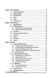
......87 4-6 Q-Share ...88 4-7 Time Repair ...89 4-8 Teaming ...90 Chapter 5 Appendix ...91 5-1 Configuring SATA Hard Drive(s 91 5-1-1 Configuring Intel ICH10R SATA Controllers 91 5-1-2 Configuring GIGABYTE SATA2/JMB322 SATA Controller 97 5-1-3 Making a SATA RAID/AHCI Driver Diskette 99 5-1-4 Installing the SATA RAID/AHCI Driver and Operating System 101 5-1-5 Smart Backup Utility... the Sound Recorder 114 5-3 Troubleshooting 115 5-3-1 Frequently Asked Questions 115 5-3-2 Troubleshooting Procedure 116 5-4 POST Error Code 118 5-5 Regulatory Statements 122 "*" Only for GA-EX58-UD5P. - 5 -
......87 4-6 Q-Share ...88 4-7 Time Repair ...89 4-8 Teaming ...90 Chapter 5 Appendix ...91 5-1 Configuring SATA Hard Drive(s 91 5-1-1 Configuring Intel ICH10R SATA Controllers 91 5-1-2 Configuring GIGABYTE SATA2/JMB322 SATA Controller 97 5-1-3 Making a SATA RAID/AHCI Driver Diskette 99 5-1-4 Installing the SATA RAID/AHCI Driver and Operating System 101 5-1-5 Smart Backup Utility... the Sound Recorder 114 5-3 Troubleshooting 115 5-3-1 Frequently Asked Questions 115 5-3-2 Troubleshooting Procedure 116 5-4 POST Error Code 118 5-5 Regulatory Statements 122 "*" Only for GA-EX58-UD5P. - 5 -

Manual
Page 6
... IEEE 1394a bracket (Part No. 12CF1-1IE008-0*R) 2-port SATA power cable (Part No. 12CF1-2SERPW-0*R) S/PDIF in cable (Part No. 12CR1-1SPDIN-0*R) - 6 - Box Contents GA-EX58-UD5P/GA-EX58-UD5 motherboard Motherboard driver disk User's Manual Quick Installation Guide One IDE cable Four SATA 3Gb/s cables One SATA bracket I/O shield 2-Way SLI bridge connector 3-Way...
... IEEE 1394a bracket (Part No. 12CF1-1IE008-0*R) 2-port SATA power cable (Part No. 12CF1-2SERPW-0*R) S/PDIF in cable (Part No. 12CR1-1SPDIN-0*R) - 6 - Box Contents GA-EX58-UD5P/GA-EX58-UD5 motherboard Motherboard driver disk User's Manual Quick Installation Guide One IDE cable Four SATA 3Gb/s cables One SATA bracket I/O shield 2-Way SLI bridge connector 3-Way...
Manual
Page 7
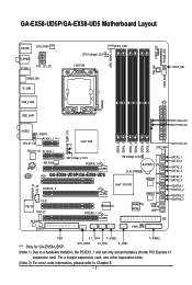
... NB_FAN NB Voltage L1/2/3 PCIEX16_1 PCI1 GA-EX58-UD5P/GA-EX58-UD5 PCIEX16_2 DDR3_2 DDR3_1 DDR3_4 DDR3_3 DDR3_6 DDR3_5 SYS_FAN1 SB Voltage L1/2/3 BATTERY CLR_CMOS Intel® ICH10R JMB322 JMB322 PCI2 IT8720 TPM_IC* M_BIOS B_BIOS TSB43AB23 PCIEX8_1 GIGABYTE SATA2 PWR_LED CI Debug LED(Note 2)... accommodate a shorter PCI Express x1 expansion card. SYS_FAN2 F2_1394 F_USB1 (Note 1) Due to Chapter 5. - 7 - GA-EX58-UD5P/GA-EX58-UD5 Motherboard Layout KB_MS SYS_FAN3 R_SPDIF V1394-1 ATX_12V_2X CMOS_SW R_USB CPU Voltage L1/2/3 LGA1366 CPU_FAN CPU TEMP L1/2 PW_SW FREQ.
... NB_FAN NB Voltage L1/2/3 PCIEX16_1 PCI1 GA-EX58-UD5P/GA-EX58-UD5 PCIEX16_2 DDR3_2 DDR3_1 DDR3_4 DDR3_3 DDR3_6 DDR3_5 SYS_FAN1 SB Voltage L1/2/3 BATTERY CLR_CMOS Intel® ICH10R JMB322 JMB322 PCI2 IT8720 TPM_IC* M_BIOS B_BIOS TSB43AB23 PCIEX8_1 GIGABYTE SATA2 PWR_LED CI Debug LED(Note 2)... accommodate a shorter PCI Express x1 expansion card. SYS_FAN2 F2_1394 F_USB1 (Note 1) Due to Chapter 5. - 7 - GA-EX58-UD5P/GA-EX58-UD5 Motherboard Layout KB_MS SYS_FAN3 R_SPDIF V1394-1 ATX_12V_2X CMOS_SW R_USB CPU Voltage L1/2/3 LGA1366 CPU_FAN CPU TEMP L1/2 PW_SW FREQ.
Manual
Page 8
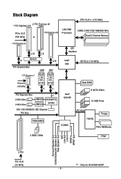
... PCIe CLK (100 MHz) x1 LAN2 LAN1 RJ45 RJ45 RTL RTL 8111D 8111D x1 x1 PCI Express Bus 2 SATA 3Gb/s 2 SATA 3Gb/s JMB322 JMB322 x1 GIGABYTE SATA2 ATA-133/100/66/33 IDE Channel PCI Bus TSB43AB23 QPI Interface Intel® X58 IOH CLK (133 MHz) Intel® ICH10R Dual BIOS... Speaker Out Center/Subwoofer Speaker Out Side Speaker Out MIC Line-Out Line-In SPDIF In SPDIF Out 2 PCI PCI CLK (33 MHz) "*" Only for GA-EX58-UD5P. - 8 -
... PCIe CLK (100 MHz) x1 LAN2 LAN1 RJ45 RJ45 RTL RTL 8111D 8111D x1 x1 PCI Express Bus 2 SATA 3Gb/s 2 SATA 3Gb/s JMB322 JMB322 x1 GIGABYTE SATA2 ATA-133/100/66/33 IDE Channel PCI Bus TSB43AB23 QPI Interface Intel® X58 IOH CLK (133 MHz) Intel® ICH10R Dual BIOS... Speaker Out Center/Subwoofer Speaker Out Side Speaker Out MIC Line-Out Line-In SPDIF In SPDIF Out 2 PCI PCI CLK (33 MHz) "*" Only for GA-EX58-UD5P. - 8 -
Manual
Page 9
If you are connected tightly and securely. • When handling the motherboard, avoid touching any installation steps or have it on top of an antistatic pad or within an electrostatic shielding container. • Before unplugging the power supply cable from the power outlet before installing or removing the motherboard or other hardware components. • When connecting hardware components to the internal connectors on the power, make sure they are uncertain about any metal leads or connectors. • It is best to the user. • If you do not have an ESD wrist strap, ...
If you are connected tightly and securely. • When handling the motherboard, avoid touching any installation steps or have it on top of an antistatic pad or within an electrostatic shielding container. • Before unplugging the power supply cable from the power outlet before installing or removing the motherboard or other hardware components. • When connecting hardware components to the internal connectors on the power, make sure they are uncertain about any metal leads or connectors. • It is best to the user. • If you do not have an ESD wrist strap, ...

Manual
Page 10
... memory (Note 1) Dual/3 channel memory architecture Support for DDR3 2100/1333/1066/800 MHz memory modules (Go to GIGABYTE's website for the latest memory support list.) Realtek ALC889A codec High Definition Audio 2/4/5.1/7.1-channel Support ... iTE IT8720 chip: - 1 x floppy disk drive connector supporting up to the internal IEEE 1394a headers) GA-EX58-UD5P/UD5 Motherboard - 10 - Support for SATA RAID 0, RAID 1, RAID 5, and RAID 10 GIGABYTE SATA2 chip: - 1 x IDE connector supporting ATA-133/100/66/33 and up to 2 IDE devices...
... memory (Note 1) Dual/3 channel memory architecture Support for DDR3 2100/1333/1066/800 MHz memory modules (Go to GIGABYTE's website for the latest memory support list.) Realtek ALC889A codec High Definition Audio 2/4/5.1/7.1-channel Support ... iTE IT8720 chip: - 1 x floppy disk drive connector supporting up to the internal IEEE 1394a headers) GA-EX58-UD5P/UD5 Motherboard - 10 - Support for SATA RAID 0, RAID 1, RAID 5, and RAID 10 GIGABYTE SATA2 chip: - 1 x IDE connector supporting ATA-133/100/66/33 and up to 2 IDE devices...
Manual
Page 11
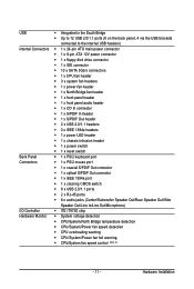
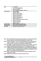
Hardware Installation USB Integrated in the South Bridge Up to 12 USB 2.0/1.1 ports (8 on the back panel, 4 via the USB brackets connected to the internal USB headers) Internal Connectors 1 x 24-pin ATX main power connector 1 x 8-pin ATX 12V power connector 1 x floppy disk drive connector 1 x IDE connector 10 x SATA 3Gb/s connectors 1 x CPU fan header 3 x system fan headers 1 x power fan header 1 x North Bridge fan header 1 x front panel header 1 x front panel audio ...
Hardware Installation USB Integrated in the South Bridge Up to 12 USB 2.0/1.1 ports (8 on the back panel, 4 via the USB brackets connected to the internal USB headers) Internal Connectors 1 x 24-pin ATX main power connector 1 x 8-pin ATX 12V power connector 1 x floppy disk drive connector 1 x IDE connector 10 x SATA 3Gb/s connectors 1 x CPU fan header 3 x system fan headers 1 x power fan header 1 x North Bridge fan header 1 x front panel header 1 x front panel audio ...
Manual
Page 12
... for how to install it is supported will depend on the CPU/ system cooler you install them in EasyTune may differ by motherboard model. GA-EX58-UD5P/UD5 Motherboard - 12 - BIOS Unique Features Bundled Software Operating System Form Factor 2 x 8 Mbit flash Use of physical ...Support for Ultra TPM* Support for Time Repair Support for Q-Share Norton Internet Security (OEM version) Support for GA-EX58-UD5P. "*" Only for Microsoft® Windows® Vista/XP ATX Form Factor; 30.5cm x 24.4cm (Note 1) Due to Windows Vista...
... for how to install it is supported will depend on the CPU/ system cooler you install them in EasyTune may differ by motherboard model. GA-EX58-UD5P/UD5 Motherboard - 12 - BIOS Unique Features Bundled Software Operating System Form Factor 2 x 8 Mbit flash Use of physical ...Support for Ultra TPM* Support for Time Repair Support for Q-Share Norton Internet Security (OEM version) Support for GA-EX58-UD5P. "*" Only for Microsoft® Windows® Vista/XP ATX Form Factor; 30.5cm x 24.4cm (Note 1) Due to Windows Vista...
Manual
Page 13
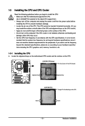
... CPU support list.) • Always turn on the computer if the CPU cooler is not recom- mended that the motherboard supports the CPU. (Go to GIGABYTE's website for the peripherals. Hardware Installation It is not installed, otherwise overheating and damage of the CPU may occur. • Set the CPU host frequency...
... CPU support list.) • Always turn on the computer if the CPU cooler is not recom- mended that the motherboard supports the CPU. (Go to GIGABYTE's website for the peripherals. Hardware Installation It is not installed, otherwise overheating and damage of the CPU may occur. • Set the CPU host frequency...
Manual
Page 14
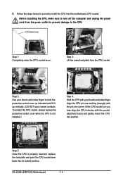
... the protective socket cover when the CPU is properly inserted, replace the load plate and push the CPU socket lever back into its locked position. GA-EX58-UD5P/UD5 Motherboard - 14 - Before installing the CPU, make sure to the CPU. B. Align the CPU pin one marking (triangle) with the pin one corner of...
... the protective socket cover when the CPU is properly inserted, replace the load plate and push the CPU socket lever back into its locked position. GA-EX58-UD5P/UD5 Motherboard - 14 - Before installing the CPU, make sure to the CPU. B. Align the CPU pin one marking (triangle) with the pin one corner of...
Manual
Page 15
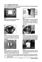
1-3-2 Installing the CPU Cooler Follow the steps below to correctly install the CPU cooler on the motherboard. (The following procedure uses Intel® boxed cooler as the picture above shows, the installation is to the CPU fan header (CPU_FAN) on installing the cooler.) Step 5: After the installation, check the back of the installed CPU. Use extreme care when removing the CPU cooler because the thermal grease/tape between the CPU cooler and CPU may damage the CPU. - 15 - Check that the Male and Female push pins are joined closely. (Refer to the CPU. If the push pin is ...
1-3-2 Installing the CPU Cooler Follow the steps below to correctly install the CPU cooler on the motherboard. (The following procedure uses Intel® boxed cooler as the picture above shows, the installation is to the CPU fan header (CPU_FAN) on installing the cooler.) Step 5: After the installation, check the back of the installed CPU. Use extreme care when removing the CPU cooler because the thermal grease/tape between the CPU cooler and CPU may damage the CPU. - 15 - Check that the Male and Female push pins are joined closely. (Refer to the CPU. If the push pin is ...

Manual
Page 16
...Channel mode. DS/SS - - When enabling 3 Channel mode with three, four or six modules, it is installed, the BIOS will appear during the POST. GA-EX58-UD5P/UD5 Motherboard - 16 - If you begin to install them in the DDR3_1, DDR3_3 and DDR3_5 sockets. DS/SS DS/SS DS/SS DS/SS (SS=Single...four modules, it in the DDR3_1 or DDR3_3. • When memory modules of the same capacity, brand, speed, and chips be used. (Go to GIGABYTE's website for the latest memory support list.) • Always turn off the computer and unplug the power cord from the power outlet before installing the...
...Channel mode. DS/SS - - When enabling 3 Channel mode with three, four or six modules, it is installed, the BIOS will appear during the POST. GA-EX58-UD5P/UD5 Motherboard - 16 - If you begin to install them in the DDR3_1, DDR3_3 and DDR3_5 sockets. DS/SS DS/SS DS/SS DS/SS (SS=Single...four modules, it in the DDR3_1 or DDR3_3. • When memory modules of the same capacity, brand, speed, and chips be used. (Go to GIGABYTE's website for the latest memory support list.) • Always turn off the computer and unplug the power cord from the power outlet before installing the...
Manual
Page 17
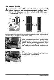
1-4-2 Installing a Memory Before installing a memory module , make sure to turn off the computer and unplug the power cord from the power outlet to prevent damage to install DDR3 DIMMs on the socket. Step 2: The clips at both ends of the memory module. Notch DDR3 DIMM A DDR3 memory module has a notch, so it vertically into place when the memory module is securely inserted. - 17 - Follow the steps below to correctly install your fingers on the memory and insert it can only fit in the memory sockets. Step 1: Note the orientation of the socket will snap into the memory ...
1-4-2 Installing a Memory Before installing a memory module , make sure to turn off the computer and unplug the power cord from the power outlet to prevent damage to install DDR3 DIMMs on the socket. Step 2: The clips at both ends of the memory module. Notch DDR3 DIMM A DDR3 memory module has a notch, so it vertically into place when the memory module is securely inserted. - 17 - Follow the steps below to correctly install your fingers on the memory and insert it can only fit in the memory sockets. Step 1: Note the orientation of the socket will snap into the memory ...
Manual
Page 18
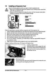
... the PCI Express slot to release the card and then pull the card straight up from the slot. Align the card with your operating system. GA-EX58-UD5P/UD5 Motherboard - 18 - If necessary, go to BIOS Setup to make any required BIOS changes for your card. Install the driver provided with a screw. 5. 1-5 Installing...
... the PCI Express slot to release the card and then pull the card straight up from the slot. Align the card with your operating system. GA-EX58-UD5P/UD5 Motherboard - 18 - If necessary, go to BIOS Setup to make any required BIOS changes for your card. Install the driver provided with a screw. 5. 1-5 Installing...

Manual
Page 19
Installation Notices: 3-1 If you use is recommended.) 3-3 To set up a 3-Way SLI configuration (Figure 1) or a 3-W ay CrossFireX configuration (Figure 2), be sure to use three identical graphics cards based on the PCIEX16_1 slot. 3-2 To set up a single graphics card system, we recommend installing the graphics card on the following GPUs and a power supply of at least 20A 5V and 12V current and a minimum of NVIDIA SLI (Scalable Link Interface)/ATI CrossFireX Configuration The SLI and CrossFireX technologies offer blistering graphics performance with the ability to bridge two or three ...
Installation Notices: 3-1 If you use is recommended.) 3-3 To set up a 3-Way SLI configuration (Figure 1) or a 3-W ay CrossFireX configuration (Figure 2), be sure to use three identical graphics cards based on the PCIEX16_1 slot. 3-2 To set up a single graphics card system, we recommend installing the graphics card on the following GPUs and a power supply of at least 20A 5V and 12V current and a minimum of NVIDIA SLI (Scalable Link Interface)/ATI CrossFireX Configuration The SLI and CrossFireX technologies offer blistering graphics performance with the ability to bridge two or three ...
Manual
Page 20
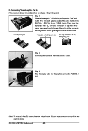
... securely fit onto the SLI gold edge connetors of three cards. Connecting Three Graphics Cards: (The procedure below demonstrates how to the three graphics cards. GA-EX58-UD5P/UD5 Motherboard - 20 - Then, insert the SLI bridge in "1-5 Installing an Expansion Card" and install three SLI-ready graphics cards of the three cards. Make...
... securely fit onto the SLI gold edge connetors of three cards. Connecting Three Graphics Cards: (The procedure below demonstrates how to the three graphics cards. GA-EX58-UD5P/UD5 Motherboard - 20 - Then, insert the SLI bridge in "1-5 Installing an Expansion Card" and install three SLI-ready graphics cards of the three cards. Make...
