Manual
Page 1
GA-EX58-UD4P LGA1366 socket motherboard for Intel® CoreTM i7 processor family User's Manual Rev. 1004 12ME-EX58UD4-1004R
GA-EX58-UD4P LGA1366 socket motherboard for Intel® CoreTM i7 processor family User's Manual Rev. 1004 12ME-EX58UD4-1004R
Manual
Page 2
Motherboard GA-EX58-UD4P Dec. 8, 2008 Motherboard GA-EX58-UD4P Dec. 8, 2008
Motherboard GA-EX58-UD4P Dec. 8, 2008 Motherboard GA-EX58-UD4P Dec. 8, 2008

Manual
Page 4
Table of Contents Box Contents ...6 OptionalItems ...6 GA-EX58-UD4P Motherboard Layout 7 Block Diagram ...8 Chapter 1 Hardware Installation 9 1-1 Installation Precautions 9 1-2 Product Specifications 10 1-3 Installing the CPU and CPU Cooler 13 1-3-1 Installing the CPU 13 1-3-2 Installing the ...
Table of Contents Box Contents ...6 OptionalItems ...6 GA-EX58-UD4P Motherboard Layout 7 Block Diagram ...8 Chapter 1 Hardware Installation 9 1-1 Installation Precautions 9 1-2 Product Specifications 10 1-3 Installing the CPU and CPU Cooler 13 1-3-1 Installing the CPU 13 1-3-2 Installing the ...
Manual
Page 6
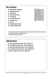
Box Contents GA-EX58-UD4P motherboard Motherboard driver disk User's Manual Quick Installation Guide One IDE cable Four SATA 3Gb/s cables One SATA bracket I/O shield 2-Way SLI bridge connector 3-Way ...
Box Contents GA-EX58-UD4P motherboard Motherboard driver disk User's Manual Quick Installation Guide One IDE cable Four SATA 3Gb/s cables One SATA bracket I/O shield 2-Way SLI bridge connector 3-Way ...
Manual
Page 7
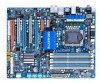
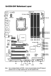
...TEMP L1/2 AUDIO F_AUDIO PCIEX1_1 (Note) Intel® X58 RTL8111D PCIEX4_1 SPDIF_I NB_FAN CODEC PCI1 NB Voltage L1/2/3 PCIEX16_1 GA-EX58-UD4P PCIEX16_2 DDR Voltage LED DDR PHASE LED DDR3_2 DDR3_1 DDR3_4 DDR3_3 DDR3_6 DDR3_5 SYS_FAN1 NB PHASE LED SB Voltage L1/2/3 BATTERY ...CLR_CMOS Intel® ICH10R SATA2_1 SATA2_0 SATA2_3 SATA2_2 SATA2_5 SATA2_4 SPDIF_O CD_IN PCI2 IT8720 TPM_IC M_BIOS B_BIOS FDD TSB43AB23 PCIEX8_1 GIGABYTE SATA2 PWR_LED GSATA2_1 GSATA2_0 CI IDE F1_1394 F_USB2 SYS_FAN2 F2_1394 F_USB1 F_PANEL (Note) Due to a hardware limitation, the PCIEX1_1 ...
...TEMP L1/2 AUDIO F_AUDIO PCIEX1_1 (Note) Intel® X58 RTL8111D PCIEX4_1 SPDIF_I NB_FAN CODEC PCI1 NB Voltage L1/2/3 PCIEX16_1 GA-EX58-UD4P PCIEX16_2 DDR Voltage LED DDR PHASE LED DDR3_2 DDR3_1 DDR3_4 DDR3_3 DDR3_6 DDR3_5 SYS_FAN1 NB PHASE LED SB Voltage L1/2/3 BATTERY ...CLR_CMOS Intel® ICH10R SATA2_1 SATA2_0 SATA2_3 SATA2_2 SATA2_5 SATA2_4 SPDIF_O CD_IN PCI2 IT8720 TPM_IC M_BIOS B_BIOS FDD TSB43AB23 PCIEX8_1 GIGABYTE SATA2 PWR_LED GSATA2_1 GSATA2_0 CI IDE F1_1394 F_USB2 SYS_FAN2 F2_1394 F_USB1 F_PANEL (Note) Due to a hardware limitation, the PCIEX1_1 ...

Manual
Page 10
... connector supporting up to 1 floppy disk drive T.I. Support for SATA RAID 0, RAID 1, RAID 5, and RAID 10 GIGABYTE SATA2 chip: - 1 x IDE connector supporting ATA-133/100/66/33 and up to 2 IDE devices - 2 x SATA 3Gb/s...; Dual/3 channel memory architecture Support for DDR3 2100/1333/1066/800 MHz memory modules (Go to GIGABYTE's website for the latest memory support list.) Realtek ALC889A codec High Definition Audio ...SATA2_1, SATA2_2, SATA2_3, SATA2_4, SATA2_5) supporting up to the internal IEEE 1394a headers) GA-EX58-UD4P Motherboard - 10 -
... connector supporting up to 1 floppy disk drive T.I. Support for SATA RAID 0, RAID 1, RAID 5, and RAID 10 GIGABYTE SATA2 chip: - 1 x IDE connector supporting ATA-133/100/66/33 and up to 2 IDE devices - 2 x SATA 3Gb/s...; Dual/3 channel memory architecture Support for DDR3 2100/1333/1066/800 MHz memory modules (Go to GIGABYTE's website for the latest memory support list.) Realtek ALC889A codec High Definition Audio ...SATA2_1, SATA2_2, SATA2_3, SATA2_4, SATA2_5) supporting up to the internal IEEE 1394a headers) GA-EX58-UD4P Motherboard - 10 -

Manual
Page 12
... install. (Note 5) Available functions in the PCIEX16_1 slot; if you are installing two PCI Express graphics cards, it in EasyTune may differ by motherboard model. GA-EX58-UD4P Motherboard - 12 -
... install. (Note 5) Available functions in the PCIEX16_1 slot; if you are installing two PCI Express graphics cards, it in EasyTune may differ by motherboard model. GA-EX58-UD4P Motherboard - 12 -
Manual
Page 14
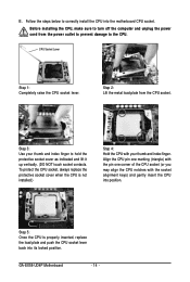
...) with the pin one corner of the CPU socket (or you may align the CPU notches with your thumb and index finger to the CPU. GA-EX58-UD4P Motherboard - 14 - Before installing the CPU, make sure to correctly install the CPU into position. To protect the CPU socket, always replace the protective socket...
...) with the pin one corner of the CPU socket (or you may align the CPU notches with your thumb and index finger to the CPU. GA-EX58-UD4P Motherboard - 14 - Before installing the CPU, make sure to correctly install the CPU into position. To protect the CPU socket, always replace the protective socket...

Manual
Page 16
.... Dual Channel-1. When enabling 3 Channel mode with three, four or six modules, it is recommended that memory of the memory. GA-EX58-UD4P Motherboard - 16 - The six DDR3 memory sockets are unable to GIGABYTE's website for the latest memory support list.) • Always turn off the computer and unplug the power cord from the...
.... Dual Channel-1. When enabling 3 Channel mode with three, four or six modules, it is recommended that memory of the memory. GA-EX58-UD4P Motherboard - 16 - The six DDR3 memory sockets are unable to GIGABYTE's website for the latest memory support list.) • Always turn off the computer and unplug the power cord from the...

Manual
Page 18
... does not rock. • Removing the Card: Press the white latch at the end of the PCI Express slot to correctly install your operating system. GA-EX58-UD4P Motherboard - 18 - After installing all expansion cards, replace the chassis cover(s). 6. Example: Installing and Removing a PCI Express x16 Graphics Card: • Installing a Graphics Card: Gently...
... does not rock. • Removing the Card: Press the white latch at the end of the PCI Express slot to correctly install your operating system. GA-EX58-UD4P Motherboard - 18 - After installing all expansion cards, replace the chassis cover(s). 6. Example: Installing and Removing a PCI Express x16 Graphics Card: • Installing a Graphics Card: Gently...
Manual
Page 20
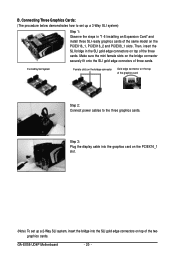
...-ready graphics cards of the same model on top of the two graphics cards. Make sure the mini female slots on top of three cards. GA-EX58-UD4P Motherboard - 20 - Step 3: Plug the display cable into the graphics card on the PCIEX16_1 slot. (Note) To set up a 2-Way SLI system, insert the bridge...
...-ready graphics cards of the same model on top of the two graphics cards. Make sure the mini female slots on top of three cards. GA-EX58-UD4P Motherboard - 20 - Step 3: Plug the display cable into the graphics card on the PCIEX16_1 slot. (Note) To set up a 2-Way SLI system, insert the bridge...
Manual
Page 22
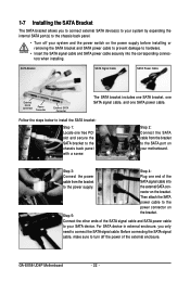
GA-EX58-UD4P Motherboard - 22 - Step 3: Step 4: Connect the power Plug one end of the cable from the bracket to the SATA port on your system and the ...
GA-EX58-UD4P Motherboard - 22 - Step 3: Step 4: Connect the power Plug one end of the cable from the bracket to the SATA port on your system and the ...

Manual
Page 24
... an optical drive, walkman, etc. Use this audio jack for a headphone or 2-channel speaker. Mic In Jack (Pink) The default Mic in a 4/5.1/7.1-channel audio configuration. GA-EX58-UD4P Motherboard - 24 - Line Out Jack (Green) The default line out jack. In addition to the default speakers settings, the ~ audio jacks can be connected to...
... an optical drive, walkman, etc. Use this audio jack for a headphone or 2-channel speaker. Mic In Jack (Pink) The default Mic in a 4/5.1/7.1-channel audio configuration. GA-EX58-UD4P Motherboard - 24 - Line Out Jack (Green) The default line out jack. In addition to the default speakers settings, the ~ audio jacks can be connected to...

Manual
Page 26
PW_SW: Power switch RST_SW: Reset switch CMOS_SW: Clearing CMOS switch GA-EX58-UD4P Motherboard - 26 - Quick Switches This motherboard has 3 quick switches: power switch, reset switch and clearing CMOS switch, allowing users to quickly turn on/off or reset the system or clear the CMOS values.
PW_SW: Power switch RST_SW: Reset switch CMOS_SW: Clearing CMOS switch GA-EX58-UD4P Motherboard - 26 - Quick Switches This motherboard has 3 quick switches: power switch, reset switch and clearing CMOS switch, allowing users to quickly turn on/off or reset the system or clear the CMOS values.

Manual
Page 28
.../Off) GND GND GND -5V +5V +5V +5V (Only for 2x12 pin ATX) GND (Only for 2x4 pin 12V) 7 +12V 8 +12V 12 24 1 13 ATX GA-EX58-UD4P Motherboard ATX : Pin No. 1 2 3 4 5 6 7 8 9 10 11 12 Definition Pin No. 3.3V 13 3.3V 14 GND 15 +5V 16 GND 17 +5V 18 GND 19 Power...
.../Off) GND GND GND -5V +5V +5V +5V (Only for 2x12 pin ATX) GND (Only for 2x4 pin 12V) 7 +12V 8 +12V 12 24 1 13 ATX GA-EX58-UD4P Motherboard ATX : Pin No. 1 2 3 4 5 6 7 8 9 10 11 12 Definition Pin No. 3.3V 13 3.3V 14 GND 15 +5V 16 GND 17 +5V 18 GND 19 Power...

Manual
Page 30
... (for example, master or slave). (For information about configuring master/slave settings for the IDE devices, read the instructions from the device manufacturers.) 39 1 40 2 GA-EX58-UD4P Motherboard - 30 - If you wish to connect two IDE devices, remember to set the jumpers and the cabling according to locate pin 1 of the connector...
... (for example, master or slave). (For information about configuring master/slave settings for the IDE devices, read the instructions from the device manufacturers.) 39 1 40 2 GA-EX58-UD4P Motherboard - 30 - If you wish to connect two IDE devices, remember to set the jumpers and the cabling according to locate pin 1 of the connector...

Manual
Page 32
...S0 On S1 Blinking S3/S4/S5 Off The LED is off when the system is in S3/S4 sleep state or powered off (S5). 1 GA-EX58-UD4P Motherboard - 32 - Each SATA connector supports a single SATA device. Refer to SATA 3Gb/s standard and are compatible with SATA 1.5Gb/s standard....This header can be used to connect a system power LED on the chassis to your SATA hard drive. 10) GSATA2_0/1 (SATA 3Gb/s Connectors, Controlled by GIGABYTE SATA2, White) The SATA connectors conform to Chapter 5, "Configuring SATA Hard Drive(s)," for instructions on when the system is operating. Pin No. 1 2 3...
...S0 On S1 Blinking S3/S4/S5 Off The LED is off when the system is in S3/S4 sleep state or powered off (S5). 1 GA-EX58-UD4P Motherboard - 32 - Each SATA connector supports a single SATA device. Refer to SATA 3Gb/s standard and are compatible with SATA 1.5Gb/s standard....This header can be used to connect a system power LED on the chassis to your SATA hard drive. 10) GSATA2_0/1 (SATA 3Gb/s Connectors, Controlled by GIGABYTE SATA2, White) The SATA connectors conform to Chapter 5, "Configuring SATA Hard Drive(s)," for instructions on when the system is operating. Pin No. 1 2 3...

Manual
Page 34
... connection between the module connector and the motherboard header will be present on each wire instead of the motherboard header. Definition 1 1 CD-L 2 GND 3 GND 4 CD-R GA-EX58-UD4P Motherboard - 34 - Pin No. You may connect the audio cable that has separated connectors on both of the front and back panel audio connections simultaneously...
... connection between the module connector and the motherboard header will be present on each wire instead of the motherboard header. Definition 1 1 CD-L 2 GND 3 GND 4 CD-R GA-EX58-UD4P Motherboard - 34 - Pin No. You may connect the audio cable that has separated connectors on both of the front and back panel audio connections simultaneously...

Manual
Page 36
GA-EX58-UD4P Motherboard - 36 - Each IEEE 1394a header can provide two USB ports via an optional IEEE 1394a bracket. Pin No. Ensure that the cable is securely ...
GA-EX58-UD4P Motherboard - 36 - Each IEEE 1394a header can provide two USB ports via an optional IEEE 1394a bracket. Pin No. Ensure that the cable is securely ...

Manual
Page 38
... a screwdriver to touch the positive and negative terminals of the battery holder, making them short for 5 seconds.) 3. The higher the CPU loading, the more details. GA-EX58-UD4P Motherboard - 38 - Refer to Chapter 4, "Dynamic Energy Saver Advanced," for one . Turn off your computer and unplug the power cord before replacing the battery. •...
... a screwdriver to touch the positive and negative terminals of the battery holder, making them short for 5 seconds.) 3. The higher the CPU loading, the more details. GA-EX58-UD4P Motherboard - 38 - Refer to Chapter 4, "Dynamic Energy Saver Advanced," for one . Turn off your computer and unplug the power cord before replacing the battery. •...

