Manual
Page 9
... break motherboard S/N (Serial Number) sticker or warranty sticker provided by unplugging the power cord from the motherboard, make sure the power supply has been turned off. • Before turning on the power, make sure they are connected tightly and securely. • When handling the... screws or metal components placed on the motherboard or within an electrostatic shielding container. • Before unplugging the power supply cable from the power outlet before installing or removing the motherboard or other hardware components. • When connecting hardware components to the ...
... break motherboard S/N (Serial Number) sticker or warranty sticker provided by unplugging the power cord from the motherboard, make sure the power supply has been turned off. • Before turning on the power, make sure they are connected tightly and securely. • When handling the... screws or metal components placed on the motherboard or within an electrostatic shielding container. • Before unplugging the power supply cable from the power outlet before installing or removing the motherboard or other hardware components. • When connecting hardware components to the ...
Manual
Page 19
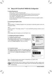
... Step 1: Observe the steps in the operating system, go to the manual of the two cards. System Requirements - A CrossFireX/SLI-supported motherboard with sufficient power is selected. A power supply with two PCI Express x16 slots and correct driver - Browse to the CrossFireX menu and ensure the Enable CrossFireX™ check box is recommended... are optional. To Enable SLI Function After installing the graphics card driver in the CrossFireX/SLI gold edge connectors on your graphics cards for the power requirement) B.
... Step 1: Observe the steps in the operating system, go to the manual of the two cards. System Requirements - A CrossFireX/SLI-supported motherboard with sufficient power is selected. A power supply with two PCI Express x16 slots and correct driver - Browse to the CrossFireX menu and ensure the Enable CrossFireX™ check box is recommended... are optional. To Enable SLI Function After installing the graphics card driver in the CrossFireX/SLI gold edge connectors on your graphics cards for the power requirement) B.

Manual
Page 23
... power, the result can supply enough stable power to all devices are compatible with power supplies with 2x2 12V and 2x10 power connectors. Connect the power supply cable to the CPU. When using a power supply providing a 2x2 12V and a 2x10 power connector. Before connecting the power connector, first make sure the power supply is used (500W or greater). The 12V power connector mainly supplies power to the power...
... power, the result can supply enough stable power to all devices are compatible with power supplies with 2x2 12V and 2x10 power connectors. Connect the power supply cable to the CPU. When using a power supply providing a 2x2 12V and a 2x10 power connector. Before connecting the power connector, first make sure the power supply is used (500W or greater). The 12V power connector mainly supplies power to the power...
Manual
Page 33
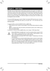
To upgrade the BIOS, use either the GIGABYTE Q-Flash or @BIOS utility. • Q-Flash allows the user to clear the CMOS values.) - 33 - Refer to Chapter 5, "Troubleshooting," for how to quickly and easily ... . To access the BIOS Setup program, press the key during system startup, saving system parameters and loading operating system, etc. When the power is turned on the motherboard supplies the necessary power to the CMOS to activate certain system features. Chapter 2 BIOS Setup BIOS (Basic Input and Output System) records hardware parameters of...
To upgrade the BIOS, use either the GIGABYTE Q-Flash or @BIOS utility. • Q-Flash allows the user to clear the CMOS values.) - 33 - Refer to Chapter 5, "Troubleshooting," for how to quickly and easily ... . To access the BIOS Setup program, press the key during system startup, saving system parameters and loading operating system, etc. When the power is turned on the motherboard supplies the necessary power to the CMOS to activate certain system features. Chapter 2 BIOS Setup BIOS (Basic Input and Output System) records hardware parameters of...
Manual
Page 55
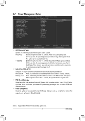
... wake-up signal from a PCI or PCIe device. BIOS Setup If the power button is pressed for 4 seconds to turn off the computer in a low power mode. Note: To use this function, you need an ATX power supply providing at any time. S1(POS) Enables the system to RAM) sleep state... (default). When signaled by Alarm x Date (of Month) Alarm x Time (hh:mm:ss) Alarm HPET Support (Note) HPET Mode (Note) Power On By Mouse Power On By Keyboard x KB Power ON Password AC...
... wake-up signal from a PCI or PCIe device. BIOS Setup If the power button is pressed for 4 seconds to turn off the computer in a low power mode. Note: To use this function, you need an ATX power supply providing at any time. S1(POS) Enables the system to RAM) sleep state... (default). When signaled by Alarm x Date (of Month) Alarm x Time (hh:mm:ss) Alarm HPET Support (Note) HPET Mode (Note) Power On By Mouse Power On By Keyboard x KB Power ON Password AC...
Manual
Page 56
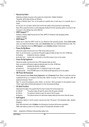
...enabled, set the date and time as following four functions will be turned on the system. Disabled Disables this function, you need an ATX power supply providing at least 1A on the +5VSB lead. Note: you to clear the password settings. When prompted for the password, press again without... entering the password to select the HPET mode for Windows Vista operating system. (Default: Enabled) HPET Mode (Note) Allows you need an ATX power supply providing at least 1A on the system, enter the password and press . BIOS Setup - 56 - Time (hh: mm: ss) Alarm: Set the...
...enabled, set the date and time as following four functions will be turned on the system. Disabled Disables this function, you need an ATX power supply providing at least 1A on the +5VSB lead. Note: you to clear the password settings. When prompted for the password, press again without... entering the password to select the HPET mode for Windows Vista operating system. (Default: Enabled) HPET Mode (Note) Allows you need an ATX power supply providing at least 1A on the system, enter the password and press . BIOS Setup - 56 - Time (hh: mm: ss) Alarm: Set the...
Manual
Page 79
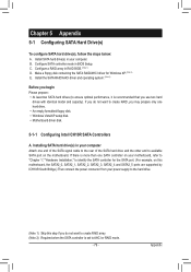
.... (For example, on this motherboard, the SATA2_0, SATA2_1, SATA2_2, SATA2_3, SATA2_4 and SATA2_5 ports are supported by ICH10R South Bridge.) Then connect the power connector from your power supply to the hard drive. (Note 1) Skip this step if you may prepare only one SATA controller on the motherboard. If you do not want...
.... (For example, on this motherboard, the SATA2_0, SATA2_1, SATA2_2, SATA2_3, SATA2_4 and SATA2_5 ports are supported by ICH10R South Bridge.) Then connect the power connector from your power supply to the hard drive. (Note 1) Skip this step if you may prepare only one SATA controller on the motherboard. If you do not want...
Manual
Page 85
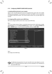
.... If you have and the BIOS version. - 85 - The BIOS Setup menus described in your power supply to IDE or AHCI. Installing SATA hard drive(s) in this motherboard, the GSATA2_0 and GSATA2_1 ports are supported by the GIGABYTE SATA2 SATA controller. B. On this section may differ from your computer Attach one end of...
.... If you have and the BIOS version. - 85 - The BIOS Setup menus described in your power supply to IDE or AHCI. Installing SATA hard drive(s) in this motherboard, the GSATA2_0 and GSATA2_1 ports are supported by the GIGABYTE SATA2 SATA controller. B. On this section may differ from your computer Attach one end of...
Manual
Page 109
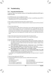
...that have a clearing CMOS jumper, refer to the instructions on . You can temporarily remove the battery from the battery holder to stop supplying power to the CMOS, which will clear the CMOS values after the computer shuts down and that have a CMOS_SW button, press this button... My Computer > Properties > Gen- A: Some motherboards provide a small amount of my keyboard/optical mouse still on GIGABYTE's website. For motherboards that 's why the light is equipped with power/amplifier. If your speaker is still on the CLR_CMOS jumper in Chapter 1. Q: Why cannot I clear the CMOS ...
...that have a clearing CMOS jumper, refer to the instructions on . You can temporarily remove the battery from the battery holder to stop supplying power to the CMOS, which will clear the CMOS values after the computer shuts down and that have a CMOS_SW button, press this button... My Computer > Properties > Gen- A: Some motherboards provide a small amount of my keyboard/optical mouse still on GIGABYTE's website. For motherboards that 's why the light is equipped with power/amplifier. If your speaker is still on the CLR_CMOS jumper in Chapter 1. Q: Why cannot I clear the CMOS ...

Manual
Page 111
... as soon as possible. - 111 - A When the computer is turned on your question. Plug in the keyboard and mouse and restart the computer. No The power supply, CPU or CPU socket might fail. Yes Check if there is working properly. No The graphics card, expansion slot, or monitor might fail. Check if...
... as soon as possible. - 111 - A When the computer is turned on your question. Plug in the keyboard and mouse and restart the computer. No The power supply, CPU or CPU socket might fail. Yes Check if there is working properly. No The graphics card, expansion slot, or monitor might fail. Check if...


