Manual
Page 3
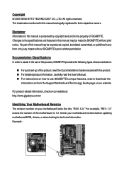
... and features in this manual may be reproduced, copied, translated, transmitted, or published in the use GIGABYTE's unique features, read or download the information on/from the Support\Motherboard\Technology Guide page on our website. No part of this manual are legally registered to assist in... trademarks mentioned in this : "REV: X.X." All rights reserved. For product-related information, check on our website at: http://www.gigabyte.com.tw Identifying Your Motherboard Revision The revision number on how to use of this manual may be made by any form or by...
... and features in this manual may be reproduced, copied, translated, transmitted, or published in the use GIGABYTE's unique features, read or download the information on/from the Support\Motherboard\Technology Guide page on our website. No part of this manual are legally registered to assist in... trademarks mentioned in this : "REV: X.X." All rights reserved. For product-related information, check on our website at: http://www.gigabyte.com.tw Identifying Your Motherboard Revision The revision number on how to use of this manual may be made by any form or by...
Manual
Page 10
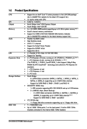
... chip: - 1 x floppy disk drive connector supporting up to 1 floppy disk drive T.I. Support for SATA RAID 0, RAID 1, RAID 5, and RAID 10 GIGABYTE SATA2 chip: - 1 x IDE connector supporting ATA-133/100/66/33 and up to 2...support 2-Way/3-Way NVIDIA SLI/ATI CrossFireXTM technology and conform to PCI Express 2.0 standard.) 1 x PCI Express x4 slot 1 x PCI Express x1 slot 2 x PCI slots South Bridge: - 6 x SATA 3Gb/s connectors (SATA2_0, SATA2_1, SATA2_2, SATA2_3, SATA2_4, SATA2_5) supporting up to the internal IEEE 1394a headers) GA-EX58-EXTREME...
... chip: - 1 x floppy disk drive connector supporting up to 1 floppy disk drive T.I. Support for SATA RAID 0, RAID 1, RAID 5, and RAID 10 GIGABYTE SATA2 chip: - 1 x IDE connector supporting ATA-133/100/66/33 and up to 2...support 2-Way/3-Way NVIDIA SLI/ATI CrossFireXTM technology and conform to PCI Express 2.0 standard.) 1 x PCI Express x4 slot 1 x PCI Express x1 slot 2 x PCI slots South Bridge: - 6 x SATA 3Gb/s connectors (SATA2_0, SATA2_1, SATA2_2, SATA2_3, SATA2_4, SATA2_5) supporting up to the internal IEEE 1394a headers) GA-EX58-EXTREME...
Manual
Page 12
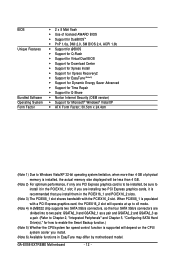
... limitation, when more than 4 GB. (Note 2) For optimum performance, if only one PCI Express graphics card is supported will be sure to x8 mode. (Note 4) A JMB322 chip supports two SATA 3Gb/s connectors, so the four SATA 3Gb/s connectors are installing two PCI Express graphics cards, it in the PCIEX16_1 slot; GA-EX58-EXTREME Motherboard - 12 -
... limitation, when more than 4 GB. (Note 2) For optimum performance, if only one PCI Express graphics card is supported will be sure to x8 mode. (Note 4) A JMB322 chip supports two SATA 3Gb/s connectors, so the four SATA 3Gb/s connectors are installing two PCI Express graphics cards, it in the PCIEX16_1 slot; GA-EX58-EXTREME Motherboard - 12 -
Manual
Page 13
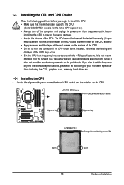
... Hardware Installation The CPU cannot be set the frequency beyond hardware specifications since it does not meet the standard requirements for the latest CPU support list.) • Always turn on the surface of the CPU. • Do not turn off the computer and unplug the power cord... Locate the alignment keys on the motherboard CPU socket and the notches on the CPU Notch Notch - 13 - mended that the motherboard supports the CPU. (Go to GIGABYTE's website for the peripherals. 1-3 Installing the CPU and CPU Cooler Read the following guidelines before you begin to install the CPU: ...
... Hardware Installation The CPU cannot be set the frequency beyond hardware specifications since it does not meet the standard requirements for the latest CPU support list.) • Always turn on the surface of the CPU. • Do not turn off the computer and unplug the power cord... Locate the alignment keys on the motherboard CPU socket and the notches on the CPU Notch Notch - 13 - mended that the motherboard supports the CPU. (Go to GIGABYTE's website for the peripherals. 1-3 Installing the CPU and CPU Cooler Read the following guidelines before you begin to install the CPU: ...
Manual
Page 17
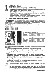
...be enabled if only one or two DDR3 memory modules are unable to be used . If you begin to GIGABYTE's website for the latest memory support list.) • Always turn off the computer and unplug the power cord from the power outlet before installing the... different memory sizes to insert the memory, switch the direction. 1-5-1 Dual/3 Channel Memory Configuration This motherboard provides six DDR3 memory sockets and supports Dual/3 Channel Technology. DDR3_5 - - - 3 Channel Memory Configurations Table Three Modules Four Modules Six Modules DDR3_2 - Hardware Installation Dual or...
...be enabled if only one or two DDR3 memory modules are unable to be used . If you begin to GIGABYTE's website for the latest memory support list.) • Always turn off the computer and unplug the power cord from the power outlet before installing the... different memory sizes to insert the memory, switch the direction. 1-5-1 Dual/3 Channel Memory Configuration This motherboard provides six DDR3 memory sockets and supports Dual/3 Channel Technology. DDR3_5 - - - 3 Channel Memory Configurations Table Three Modules Four Modules Six Modules DDR3_2 - Hardware Installation Dual or...

Manual
Page 19
... seated in the expansion slot. 1. If necessary, go to BIOS Setup to correctly install your operating system. Carefully read the manual that supports your computer. PCI Express x1 Slot PCI Express x4 Slot PCI Express x16 Slot PCI Slot Follow the steps below to make any required ...off the computer and unplug the power cord from the power outlet before you begin to install an expansion card: • Make sure the motherboard supports the expansion card. Example: Installing and Removing a PCI Express x16 Graphics Card: • Installing a Graphics Card: Gently push down on the card...
... seated in the expansion slot. 1. If necessary, go to BIOS Setup to correctly install your operating system. Carefully read the manual that supports your computer. PCI Express x1 Slot PCI Express x4 Slot PCI Express x16 Slot PCI Slot Follow the steps below to make any required ...off the computer and unplug the power cord from the power outlet before you begin to install an expansion card: • Make sure the motherboard supports the expansion card. Example: Installing and Removing a PCI Express x16 Graphics Card: • Installing a Graphics Card: Gently push down on the card...
Manual
Page 20
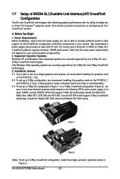
... SLI (Scalable Link Interface)/ATI CrossFireX Configuration The SLI and CrossFireX technologies offer blistering graphics performance with the ability to fully support an SLI/CrossFireX configuration and other components in Figure 2. GA-EX58-EXTREME Motherboard - 20 - Installation Notices: 3-1 If you use three identical graphics cards based on the PCIEX16_1 and PCIEX16_2 slots. (Using graphics...
... SLI (Scalable Link Interface)/ATI CrossFireX Configuration The SLI and CrossFireX technologies offer blistering graphics performance with the ability to fully support an SLI/CrossFireX configuration and other components in Figure 2. GA-EX58-EXTREME Motherboard - 20 - Installation Notices: 3-1 If you use three identical graphics cards based on the PCIEX16_1 and PCIEX16_2 slots. (Using graphics...
Manual
Page 24
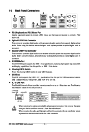
... USB Port The USB port supports the USB 2.0/1.1 specification. Use this port for USB devices such as an USB keyboard/mouse, USB printer, USB flash drive and etc. The following describes the states of the LAN port LEDs. GA-EX58-EXTREME Motherboard - 24 - Do ... coaxial digital audio in connector. Before using this feature, ensure that supports digital coaxial audio. Before using this feature, ensure that supports digital optical audio. IEEE 1394a Port The IEEE 1394 port supports the IEEE 1394a specification, featuring high speed, high bandwidth and hotplug capabilities...
... USB Port The USB port supports the USB 2.0/1.1 specification. Use this port for USB devices such as an USB keyboard/mouse, USB printer, USB flash drive and etc. The following describes the states of the LAN port LEDs. GA-EX58-EXTREME Motherboard - 24 - Do ... coaxial digital audio in connector. Before using this feature, ensure that supports digital coaxial audio. Before using this feature, ensure that supports digital optical audio. IEEE 1394a Port The IEEE 1394 port supports the IEEE 1394a specification, featuring high speed, high bandwidth and hotplug capabilities...
Manual
Page 30
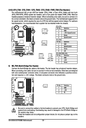
... connect it in the correct orientation (the black connector wire is the ground wire). Overheating may result in the correct orientation. GA-EX58-EXTREME Motherboard - 30 - Most fans are not configuration jumper blocks. The black connector wire is recommended that a system fan be ... headers are designed with fan speed control design. A red power connector wire indicates a positive connection and requires a +12V voltage. The motherboard supports CPU fan speed control, which requires the use of a CPU fan with color-coded power connector wires. Definition 1 GND 2 +12V 3...
... connect it in the correct orientation (the black connector wire is the ground wire). Overheating may result in the correct orientation. GA-EX58-EXTREME Motherboard - 30 - Most fans are not configuration jumper blocks. The black connector wire is recommended that a system fan be ... headers are designed with fan speed control design. A red power connector wire indicates a positive connection and requires a +12V voltage. The motherboard supports CPU fan speed control, which requires the use of a CPU fan with color-coded power connector wires. Definition 1 GND 2 +12V 3...

Manual
Page 31
... disk drive. 7) FDD (Floppy Disk Drive Connector) This connector is typically designated by a stripe of different color. 33 1 34 2 8) IDE (IDE Connector) The IDE connector supports up to the role of the IDE devices (for example, master or slave). (For information about configuring master/slave settings for the IDE devices, read... the instructions from the device manufacturers.) 39 1 40 2 - 31 - Hardware Installation The types of floppy disk drives supported are: 360 KB, 720 KB, 1.2 MB, 1.44 MB, and 2.88 MB.
... disk drive. 7) FDD (Floppy Disk Drive Connector) This connector is typically designated by a stripe of different color. 33 1 34 2 8) IDE (IDE Connector) The IDE connector supports up to the role of the IDE devices (for example, master or slave). (For information about configuring master/slave settings for the IDE devices, read... the instructions from the device manufacturers.) 39 1 40 2 - 31 - Hardware Installation The types of floppy disk drives supported are: 360 KB, 720 KB, 1.2 MB, 1.44 MB, and 2.88 MB.
Manual
Page 32
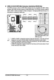
... total number of hard drives must be an even number.) • A RAID 10 configuration requires at least two hard drives. GA-EX58-EXTREME Motherboard - 32 - Each SATA connector supports a single SATA device. If more than two hard drives are compatible with SATA 1.5Gb/s standard. The ICH10R controller... supports RAID 0, RAID 1, RAID 5 and RAID 10. Refer to Chapter 5, "Configuring SATA Hard Drive(s)," for instructions on configuring a RAID array. 9) SATA2_0/1/2/3/4/5 (...
... total number of hard drives must be an even number.) • A RAID 10 configuration requires at least two hard drives. GA-EX58-EXTREME Motherboard - 32 - Each SATA connector supports a single SATA device. If more than two hard drives are compatible with SATA 1.5Gb/s standard. The ICH10R controller... supports RAID 0, RAID 1, RAID 5 and RAID 10. Refer to Chapter 5, "Configuring SATA Hard Drive(s)," for instructions on configuring a RAID array. 9) SATA2_0/1/2/3/4/5 (...

Manual
Page 33
...1 GSATA2_0 Pin No. 1 2 3 4 5 6 7 Definition GND TXP TXN GND RXN RXP GND A RAID 0 or RAID 1 configuration requires two hard drives. The GIGABYTE SATA2/JMB322 controller supports RAID 0, RAID 1 and JBOD. The two hard drives must be used to connect a system power LED on the chassis to Chapter 2, "Integrated Peripherals" and...- Pin No. 1 2 3 Definition MPD+ MPDMPD- The LED keeps blinking when the system is operating. 10) GSATA2_0/1/2/3 (SATA 3Gb/s Connectors, Controlled by GIGABYTE SATA2/JMB322, White) The SATA connectors conform to the GSATA2_2 and GSATA2_3 connectors.
...1 GSATA2_0 Pin No. 1 2 3 4 5 6 7 Definition GND TXP TXN GND RXN RXP GND A RAID 0 or RAID 1 configuration requires two hard drives. The GIGABYTE SATA2/JMB322 controller supports RAID 0, RAID 1 and JBOD. The two hard drives must be used to connect a system power LED on the chassis to Chapter 2, "Integrated Peripherals" and...- Pin No. 1 2 3 Definition MPD+ MPDMPD- The LED keeps blinking when the system is operating. 10) GSATA2_0/1/2/3 (SATA 3Gb/s Connectors, Controlled by GIGABYTE SATA2/JMB322, White) The SATA connectors conform to the GSATA2_2 and GSATA2_3 connectors.

Manual
Page 35
... has separated connectors on both of the front and back panel audio connections simultaneously. 13) F_AUDIO (Front Panel Audio Header) The front panel audio header supports Intel High Definition audio (HD) and AC'97 audio. Definition 1 1 CD-L 2 GND 3 GND 4 CD-R - 35 - Definition 1 2 1 MIC2_L Pin No. 1 Definition ...Pin 9 LINE2_L 9 Line Out (L) 10 GND 10 NC • The front panel audio header supports HD audio by default. If you want to mute the back panel audio (only supported when using an HD front panel audio module), refer to work or even damage it. For ...
... has separated connectors on both of the front and back panel audio connections simultaneously. 13) F_AUDIO (Front Panel Audio Header) The front panel audio header supports Intel High Definition audio (HD) and AC'97 audio. Definition 1 1 CD-L 2 GND 3 GND 4 CD-R - 35 - Definition 1 2 1 MIC2_L Pin No. 1 Definition ...Pin 9 LINE2_L 9 Line Out (L) 10 GND 10 NC • The front panel audio header supports HD audio by default. If you want to mute the back panel audio (only supported when using an HD front panel audio module), refer to work or even damage it. For ...
Manual
Page 36
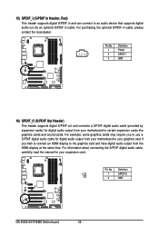
...connect an HDMI display to the graphics card and have digital audio output from your expansion card. Definition 1 1 SPDIFO 2 GND GA-EX58-EXTREME Motherboard - 36 - For information about connecting the S/PDIF digital audio cable, carefully read the manual for digital audio output from ... the optional S/PDIF in cable. Pin No. Definition 1 Power 1 2 SPDIFI 3 GND 16) SPDIF_O (S/PDIF Out Header) This header supports digital S/PDIF out and connects a S/PDIF digital audio cable (provided by expansion cards) for your motherboard to certain expansion cards like graphics ...
...connect an HDMI display to the graphics card and have digital audio output from your expansion card. Definition 1 1 SPDIFO 2 GND GA-EX58-EXTREME Motherboard - 36 - For information about connecting the S/PDIF digital audio cable, carefully read the manual for digital audio output from ... the optional S/PDIF in cable. Pin No. Definition 1 Power 1 2 SPDIFI 3 GND 16) SPDIF_O (S/PDIF Out Header) This header supports digital S/PDIF out and connects a S/PDIF digital audio cable (provided by expansion cards) for your motherboard to certain expansion cards like graphics ...
Manual
Page 45
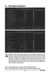
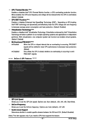
... Speed QPI Link Speed UnCore & QPI Features Base Clock(BCLK) Control x BCLK Frequency (Mhz) Advanced Clock Control Performance Enhance Extreme Memory Profile (X.M.P.) (Note 2) System Memory Multiplier (SPD) Memory Frequency (Mhz) 1066 DRAM Timing Selectable Profile DDR Voltage Profile QPI Voltage >>>>> Channel... overclock/overvoltage may result in damage to default values.) (Note 1) This item appears only if you install a CPU that supports this feature. (Note 2) This item appears only if you not to alter the default settings to prevent system instability or other...
... Speed QPI Link Speed UnCore & QPI Features Base Clock(BCLK) Control x BCLK Frequency (Mhz) Advanced Clock Control Performance Enhance Extreme Memory Profile (X.M.P.) (Note 2) System Memory Multiplier (SPD) Memory Frequency (Mhz) 1066 DRAM Timing Selectable Profile DDR Voltage Profile QPI Voltage >>>>> Channel... overclock/overvoltage may result in damage to default values.) (Note 1) This item appears only if you install a CPU that supports this feature. (Note 2) This item appears only if you not to alter the default settings to prevent system instability or other...

Manual
Page 46
... state to decrease power consumption. (Default: Enabled) C3/C6/C7 State Support (Note) Allows you to let the CPU enter C3/C6/C7 mode in system halt state. CPU Frequency Displays the current operating CPU frequency. Enabled Enables all CPU cores. GA-EX58-EXTREME Motherboard - 46 - ******* Advanced CPU Features******* CMOS Setup Utility-Copyright (C) 1984...
... state to decrease power consumption. (Default: Enabled) C3/C6/C7 State Support (Note) Allows you to let the CPU enter C3/C6/C7 mode in system halt state. CPU Frequency Displays the current operating CPU frequency. Enabled Enables all CPU cores. GA-EX58-EXTREME Motherboard - 46 - ******* Advanced CPU Features******* CMOS Setup Utility-Copyright (C) 1984...
Manual
Page 47
... Utility-Copyright (C) 1984-2008 Award Software UnCore & QPI Features QPI Link Speed QPI Link Speed(MT) Uncore Frequency Uncore Frequency(MHz) Isochronous Support [Auto] 4.8GHz [Auto] 2667 [Enabled] Item Help Menu Level Move Enter: Select F5: Previous Values +/-/PU/PD: Value ... as multiple virtual systems. (Default: Enabled) Bi-Directional PROCHOT (Note) Enabled When the CPU or chipset detects that supports this feature. - 47 - Isochronous Support Determines whether to enable specific streams between the IOH and ICH. (Default: Enabled) (Note) This item appears only if...
... Utility-Copyright (C) 1984-2008 Award Software UnCore & QPI Features QPI Link Speed QPI Link Speed(MT) Uncore Frequency Uncore Frequency(MHz) Isochronous Support [Auto] 4.8GHz [Auto] 2667 [Enabled] Item Help Menu Level Move Enter: Select F5: Previous Values +/-/PU/PD: Value ... as multiple virtual systems. (Default: Enabled) Bi-Directional PROCHOT (Note) Enabled When the CPU or chipset detects that supports this feature. - 47 - Isochronous Support Determines whether to enable specific streams between the IOH and ICH. (Default: Enabled) (Note) This item appears only if...
Manual
Page 49
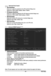
...0ps~750ps. (Default: 0ps) ******* Advanced DRAM Features******* CMOS Setup Utility-Copyright (C) 1984-2008 Award Software Advanced DRAM Features Performance Enhance Extreme Memory Profile (X.M.P.) (Note) System Memory Multiplier (SPD) Memory Frequency (Mhz) 1066 [Turbo] [Disabled] [Auto] 1066 Item Help ... Lets the system operate at its good performance level. (Default) Extreme Lets the system operate at its best performance level. >>>>> Advanced Clock Control CPU Clock Drive Allows you install a memory module that supports this feature. - 49 - Options are : 700mV, 800mV, 900mV...
...0ps~750ps. (Default: 0ps) ******* Advanced DRAM Features******* CMOS Setup Utility-Copyright (C) 1984-2008 Award Software Advanced DRAM Features Performance Enhance Extreme Memory Profile (X.M.P.) (Note) System Memory Multiplier (SPD) Memory Frequency (Mhz) 1066 [Turbo] [Disabled] [Auto] 1066 Item Help ... Lets the system operate at its good performance level. (Default) Extreme Lets the system operate at its best performance level. >>>>> Advanced Clock Control CPU Clock Drive Allows you install a memory module that supports this feature. - 49 - Options are : 700mV, 800mV, 900mV...
Manual
Page 55
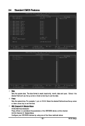
... IDE Channel 4 Slave IDE Channel 5 Master IDE Channel 5 Slave [None] [None] [None] [None] [None] [None] [None] [None] [None] [None] Drive A Floppy 3 Mode Support [1.44M, 3.5"] [Disabled] Halt On [All, But Keyboard] Move Enter: Select F5: Previous Values +/-/PU/PD: Value F10: Save F6: Fail-Safe Default ESC: Exit F1...
... IDE Channel 4 Slave IDE Channel 5 Master IDE Channel 5 Slave [None] [None] [None] [None] [None] [None] [None] [None] [None] [None] Drive A Floppy 3 Mode Support [1.44M, 3.5"] [Disabled] Halt On [All, But Keyboard] Move Enter: Select F5: Previous Values +/-/PU/PD: Value F10: Save F6: Fail-Safe Default ESC: Exit F1...
Manual
Page 56
...will not stop for a keyboard error but stop for all other errors. (Default) All, But Diskette The system boot will not stop for any error. GA-EX58-EXTREME Motherboard - 56 - Access Mode Sets the hard drive access mode. Options are : None, 360K/5.25", 1.2M/5.25", 720K/3.5", 1.44M/3.5", 2.88M/3.5".... of the IDE/SATA device on the hard drive. Capacity Approximate capacity of extended memory. Head Number of sectors. Floppy 3 Mode Support Allows you to determine whether the system will be reserved for all other errors. Halt On Allows you to specify whether the installed ...
...will not stop for a keyboard error but stop for all other errors. (Default) All, But Diskette The system boot will not stop for any error. GA-EX58-EXTREME Motherboard - 56 - Access Mode Sets the hard drive access mode. Options are : None, 360K/5.25", 1.2M/5.25", 720K/3.5", 1.44M/3.5", 2.88M/3.5".... of the IDE/SATA device on the hard drive. Capacity Approximate capacity of extended memory. Head Number of sectors. Floppy 3 Mode Support Allows you to determine whether the system will be reserved for all other errors. Halt On Allows you to specify whether the installed ...

