Manual
Page 3
....tw Identifying Your Motherboard Revision The revision number on our website. No part of the motherboard is protected by GIGABYTE without GIGABYTE's prior written permission. For example, "REV: 1.0" means the revision of this : "REV: X.X." The trademarks mentioned...: For quick set-up of GIGABYTE. Documentation Classifications In order to use GIGABYTE's unique features, read or download the information on/from the Support\Motherboard\Technology Guide page on your motherboard revision before updating motherboard BIOS, drivers, or when looking for technical information...
....tw Identifying Your Motherboard Revision The revision number on our website. No part of the motherboard is protected by GIGABYTE without GIGABYTE's prior written permission. For example, "REV: 1.0" means the revision of this : "REV: X.X." The trademarks mentioned...: For quick set-up of GIGABYTE. Documentation Classifications In order to use GIGABYTE's unique features, read or download the information on/from the Support\Motherboard\Technology Guide page on your motherboard revision before updating motherboard BIOS, drivers, or when looking for technical information...
Manual
Page 4
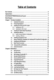
Table of Contents Box Contents ...6 OptionalItems ...6 GA-EX58-EXTREME Motherboard Layout 7 Block Diagram ...8 Chapter 1 Hardware Installation 9 1-1 Installation Precautions 9 1-2 Product Specifications 10 1-3 Installing the CPU and CPU Cooler 13 1-3-1...Panel Connectors 24 1-10 Onboard LEDs and Switches 26 1-11 Internal Connectors 28 Chapter 2 BIOS Setup 41 2-1 Startup Screen 42 2-2 The Main Menu 43 2-3 MB Intelligent Tweaker(M.I.T 45 2-4 Standard CMOS Features 55 2-5 Advanced BIOS Features 57 2-6 IntegratedPeripherals 59 2-7 Power Management Setup 64 2-8 PC Health Status 66 2-9...
Table of Contents Box Contents ...6 OptionalItems ...6 GA-EX58-EXTREME Motherboard Layout 7 Block Diagram ...8 Chapter 1 Hardware Installation 9 1-1 Installation Precautions 9 1-2 Product Specifications 10 1-3 Installing the CPU and CPU Cooler 13 1-3-1...Panel Connectors 24 1-10 Onboard LEDs and Switches 26 1-11 Internal Connectors 28 Chapter 2 BIOS Setup 41 2-1 Startup Screen 42 2-2 The Main Menu 43 2-3 MB Intelligent Tweaker(M.I.T 45 2-4 Standard CMOS Features 55 2-5 Advanced BIOS Features 57 2-6 IntegratedPeripherals 59 2-7 Power Management Setup 64 2-8 PC Health Status 66 2-9...
Manual
Page 5
...Center 74 Chapter 4 Unique Features 75 4-1 Xpress Recovery2 75 4-2 BIOS Update Utilities 78 4-2-1 Updating the BIOS with the Q-Flash Utility 78 4-2-2 Updating the BIOS with the @BIOS Utility 81 4-3 EasyTune 6 ...82 4-4 Dynamic Energy Saver Advanced ...83 4-5 Q-Share ...85 4-6 Time Repair ...86 4-7 Teaming ...87 Chapter 5 Appendix ...89 5-1 Configuring SATA Hard Drive(s 89 5-1-1 Configuring Intel ICH10R SATA Controllers 89 5-1-2 Configuring GIGABYTE...
...Center 74 Chapter 4 Unique Features 75 4-1 Xpress Recovery2 75 4-2 BIOS Update Utilities 78 4-2-1 Updating the BIOS with the Q-Flash Utility 78 4-2-2 Updating the BIOS with the @BIOS Utility 81 4-3 EasyTune 6 ...82 4-4 Dynamic Energy Saver Advanced ...83 4-5 Q-Share ...85 4-6 Time Repair ...86 4-7 Teaming ...87 Chapter 5 Appendix ...89 5-1 Configuring SATA Hard Drive(s 89 5-1-1 Configuring Intel ICH10R SATA Controllers 89 5-1-2 Configuring GIGABYTE...
Manual
Page 8
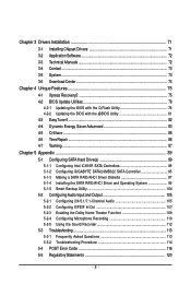
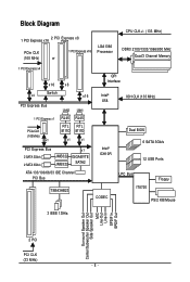
... PCIe CLK (100 MHz) x1 LAN2 LAN1 RJ45 RJ45 RTL RTL 8111D 8111D x1 x1 PCI Express Bus 2 SATA 3Gb/s 2 SATA 3Gb/s JMB322 JMB322 x1 GIGABYTE SATA2 ATA-133/100/66/33 IDE Channel PCI Bus TSB43AB23 QPI Interface Intel® X58 IOH CLK (133 MHz) Intel® ICH10R Dual... BIOS 6 SATA 3Gb/s 12 USB Ports CODEC LPC Bus IT8720 Floppy PS/2 KB/Mouse 3 IEEE 1394a Surround Speaker Out Center/Subwoofer Speaker Out Side Speaker Out ...
... PCIe CLK (100 MHz) x1 LAN2 LAN1 RJ45 RJ45 RTL RTL 8111D 8111D x1 x1 PCI Express Bus 2 SATA 3Gb/s 2 SATA 3Gb/s JMB322 JMB322 x1 GIGABYTE SATA2 ATA-133/100/66/33 IDE Channel PCI Bus TSB43AB23 QPI Interface Intel® X58 IOH CLK (133 MHz) Intel® ICH10R Dual... BIOS 6 SATA 3Gb/s 12 USB Ports CODEC LPC Bus IT8720 Floppy PS/2 KB/Mouse 3 IEEE 1394a Surround Speaker Out Center/Subwoofer Speaker Out Side Speaker Out ...
Manual
Page 12
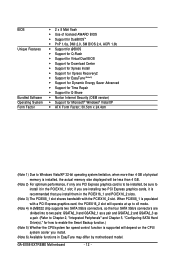
... Software Operating System Form Factor 2 x 8 Mbit flash Use of licensed AWARD BIOS Support for DualBIOSTM PnP 1.0a, DMI 2.0, SM BIOS 2.4, ACPI 1.0b Support for @BIOS Support for Q-Flash Support for Virtual Dual BIOS Support for Download Center Support for Xpress Install Support for Xpress... than 4 GB of physical memory is installed, the actual memory size displayed will be sure to install it in EasyTune may differ by motherboard model. GA-EX58-EXTREME Motherboard - 12 -
... Software Operating System Form Factor 2 x 8 Mbit flash Use of licensed AWARD BIOS Support for DualBIOSTM PnP 1.0a, DMI 2.0, SM BIOS 2.4, ACPI 1.0b Support for @BIOS Support for Q-Flash Support for Virtual Dual BIOS Support for Download Center Support for Xpress Install Support for Xpress... than 4 GB of physical memory is installed, the actual memory size displayed will be sure to install it in EasyTune may differ by motherboard model. GA-EX58-EXTREME Motherboard - 12 -
Manual
Page 17
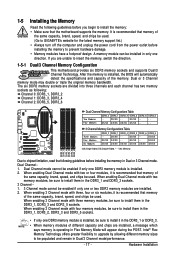
... modules are installed, a message which says memory is recommended that memory of the same capacity, brand, speed, and chips be used. (Go to GIGABYTE's website for the latest memory support list.) • Always turn off the computer and unplug the power cord from the power outlet before installing the... them in the DDR3_1 and DDR3_3 sockets. 3 Channel-1. 3 Channel mode cannot be populated and remain in only one DDR3 memory module is installed, the BIOS will appear during the POST. DS/SS DDR3_5 DS/SS DS/SS DS/SS (SS=Single-Sided, DS=Double-Sided, "- -"=No Memory) DDR3_2 DDR3_1...
... modules are installed, a message which says memory is recommended that memory of the same capacity, brand, speed, and chips be used. (Go to GIGABYTE's website for the latest memory support list.) • Always turn off the computer and unplug the power cord from the power outlet before installing the... them in the DDR3_1 and DDR3_3 sockets. 3 Channel-1. 3 Channel mode cannot be populated and remain in only one DDR3 memory module is installed, the BIOS will appear during the POST. DS/SS DDR3_5 DS/SS DS/SS DS/SS (SS=Single-Sided, DS=Double-Sided, "- -"=No Memory) DDR3_2 DDR3_1...
Manual
Page 19
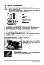
...into the slot. 4. PCI Express x1 Slot PCI Express x4 Slot PCI Express x16 Slot PCI Slot Follow the steps below to make any required BIOS changes for your expansion card in the slot. 3. Make sure the card is securely seated in the slot and does not rock. • ... power outlet before you begin to release the card and then pull the card straight up from the chassis back panel. 2. If necessary, go to BIOS Setup to correctly install your expansion card(s). 7. Example: Installing and Removing a PCI Express x16 Graphics Card: • Installing a Graphics Card: Gently push down ...
...into the slot. 4. PCI Express x1 Slot PCI Express x4 Slot PCI Express x16 Slot PCI Slot Follow the steps below to make any required BIOS changes for your expansion card in the slot. 3. Make sure the card is securely seated in the slot and does not rock. • ... power outlet before you begin to release the card and then pull the card straight up from the chassis back panel. 2. If necessary, go to BIOS Setup to correctly install your expansion card(s). 7. Example: Installing and Removing a PCI Express x16 Graphics Card: • Installing a Graphics Card: Gently push down ...

Manual
Page 34
... (S5). • PW (Power Switch, Red): Connects to the speaker on when the system is detected, the BIOS may differ by issuing a beep code. When connecting your system using the power switch (refer to Chapter 2, "BIOS Setup," "Power Management Setup," for information about beep codes. • HD (Hard Drive Activity LED, Blue... in S1 sleep state. Refer to Chapter 5, "Troubleshooting," for more information). • SPEAK (Speaker, Orange): Connects to the power switch on the chassis front panel. GA-EX58-EXTREME Motherboard - 34 -
... (S5). • PW (Power Switch, Red): Connects to the speaker on when the system is detected, the BIOS may differ by issuing a beep code. When connecting your system using the power switch (refer to Chapter 2, "BIOS Setup," "Power Management Setup," for information about beep codes. • HD (Hard Drive Activity LED, Blue... in S1 sleep state. Refer to Chapter 5, "Troubleshooting," for more information). • SPEAK (Speaker, Orange): Connects to the power switch on the chassis front panel. GA-EX58-EXTREME Motherboard - 34 -
Manual
Page 38
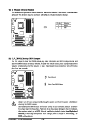
date information and BIOS configurations) and reset the CMOS values to remove the jumper cap from the power outlet before clearing... damage to the motherboard. • After system restart, go to BIOS Setup to load factory defaults (select Load Optimized Defaults) or manually configure the BIOS settings (refer to Chapter 2, "BIOS Setup," for a few seconds. GA-EX58-EXTREME Motherboard - 38 - This function requires a chassis with chassis intrusion ...1 Signal 1 2 GND 20) CLR_CMOS (Clearing CMOS Jumper) Use this jumper to touch the two pins for BIOS configurations).
date information and BIOS configurations) and reset the CMOS values to remove the jumper cap from the power outlet before clearing... damage to the motherboard. • After system restart, go to BIOS Setup to load factory defaults (select Load Optimized Defaults) or manually configure the BIOS settings (refer to Chapter 2, "BIOS Setup," for a few seconds. GA-EX58-EXTREME Motherboard - 38 - This function requires a chassis with chassis intrusion ...1 Signal 1 2 GND 20) CLR_CMOS (Clearing CMOS Jumper) Use this jumper to touch the two pins for BIOS configurations).
Manual
Page 39
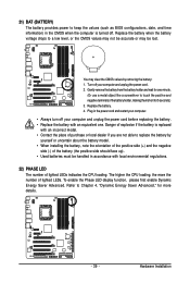
... more details. - 39 - Refer to Chapter 4, "Dynamic Energy Saver Advanced," for 5 seconds.) 3. 21) BAT (BATTERY) The battery provides power to keep the values (such as BIOS configurations, date, and time information) in the CMOS when the computer is replaced with an incorrect model. • Contact the place of purchase or local...
... more details. - 39 - Refer to Chapter 4, "Dynamic Energy Saver Advanced," for 5 seconds.) 3. 21) BAT (BATTERY) The battery provides power to keep the values (such as BIOS configurations, date, and time information) in the CMOS when the computer is replaced with an incorrect model. • Contact the place of purchase or local...
Manual
Page 41
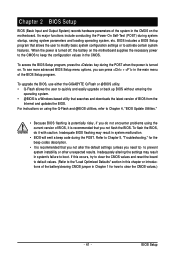
To upgrade the BIOS, use either the GIGABYTE Q-Flash or @BIOS utility. • Q-Flash allows the user to clear the CMOS values.) - 41 - Inadequate BIOS flashing may result in Chapter 1 for the beep codes description. • It is a Windows-based utility that you need ... operating system, etc. Refer to Chapter 5, "Troubleshooting," for how to quickly and easily upgrade or back up BIOS without entering the operating system. • @BIOS is recommended that allows the user to modify basic system configuration settings or to prevent system instability or other unexpected ...
To upgrade the BIOS, use either the GIGABYTE Q-Flash or @BIOS utility. • Q-Flash allows the user to clear the CMOS values.) - 41 - Inadequate BIOS flashing may result in Chapter 1 for the beep codes description. • It is a Windows-based utility that you need ... operating system, etc. Refer to Chapter 5, "Troubleshooting," for how to quickly and easily upgrade or back up BIOS without entering the operating system. • @BIOS is recommended that allows the user to modify basic system configuration settings or to prevent system instability or other unexpected ...
Manual
Page 42
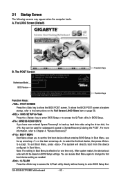
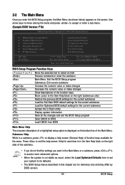
... first. The system will still be used for one time only. GA-EX58-EXTREME Motherboard - 42 - You can be based on page 58. : BIOS SETUP\Q-Flash Press the key to enter BIOS Setup or to access the Q-Flash utility in BIOS Setup. : XPRESS RECOVERY2 If you to set the first boot device without having to show...
... first. The system will still be used for one time only. GA-EX58-EXTREME Motherboard - 42 - You can be based on page 58. : BIOS SETUP\Q-Flash Press the key to enter BIOS Setup or to access the Q-Flash utility in BIOS Setup. : XPRESS RECOVERY2 If you to set the first boot device without having to show...
Manual
Page 43
..., press + to access more advanced options. • When the system is not stable as shown below) appears on the bottom line of the Main Menu. BIOS Setup Program Function Keys Move the selection bar to select an item Execute command or enter the submenu Main Menu: Exit the... BIOS Setup program Submenus: Exit current submenu Increase the numeric value or make changes Decrease the numeric value or make changes Show descriptions of the function ...
..., press + to access more advanced options. • When the system is not stable as shown below) appears on the bottom line of the Main Menu. BIOS Setup Program Function Keys Move the selection bar to select an item Execute command or enter the submenu Main Menu: Exit the... BIOS Setup program Submenus: Exit current submenu Increase the numeric value or make changes Decrease the numeric value or make changes Show descriptions of the function ...
Manual
Page 44
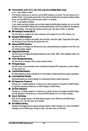
... time and date, hard drive types, floppy disk drive types, and the type of errors that stop the system boot, etc. Advanced BIOS Features Use this menu to configure the device boot order, advanced features available on the CPU, and the primary display adapter. Integrated Peripherals...Use this menu to configure all the power-saving functions. PC Health Status Use this task.) GA-EX58-EXTREME Motherboard - 44 - You can also carry out this menu to the system and BIOS Setup. An user password only allows you can also carry out this menu to make changes in effect...
... time and date, hard drive types, floppy disk drive types, and the type of errors that stop the system boot, etc. Advanced BIOS Features Use this menu to configure the device boot order, advanced features available on the CPU, and the primary display adapter. Integrated Peripherals...Use this menu to configure all the power-saving functions. PC Health Status Use this task.) GA-EX58-EXTREME Motherboard - 44 - You can also carry out this menu to the system and BIOS Setup. An user password only allows you can also carry out this menu to make changes in effect...
Manual
Page 45
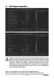
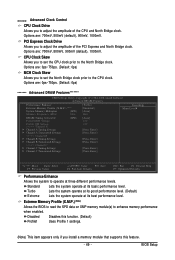
... Link Speed QPI Link Speed UnCore & QPI Features Base Clock(BCLK) Control x BCLK Frequency (Mhz) Advanced Clock Control Performance Enhance Extreme Memory Profile (X.M.P.) (Note 2) System Memory Multiplier (SPD) Memory Frequency (Mhz) 1066 DRAM Timing Selectable Profile DDR Voltage Profile QPI Voltage >>>>> Channel A... reduce the useful life of these components. If this occurs, clear the CMOS values and reset the board to boot. BIOS Setup This page is for advanced users only and we recommend you not to alter the default settings to prevent system instability...
... Link Speed QPI Link Speed UnCore & QPI Features Base Clock(BCLK) Control x BCLK Frequency (Mhz) Advanced Clock Control Performance Enhance Extreme Memory Profile (X.M.P.) (Note 2) System Memory Multiplier (SPD) Memory Frequency (Mhz) 1066 DRAM Timing Selectable Profile DDR Voltage Profile QPI Voltage >>>>> Channel A... reduce the useful life of these components. If this occurs, clear the CMOS values and reset the board to boot. BIOS Setup This page is for advanced users only and we recommend you not to alter the default settings to prevent system instability...
Manual
Page 47
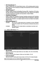
...: General Help F7: Optimized Defaults QPI Link Speed Allows you to set the QPI Link speed. Isochronous Support Determines whether to set the UnCore frequency. BIOS Setup When enabled, the CPU core frequency and voltage will allow a platform to decrease average power consumption and heat production. (Default: Enabled) Virtualization Technology (Note...
...: General Help F7: Optimized Defaults QPI Link Speed Allows you to set the QPI Link speed. Isochronous Support Determines whether to set the UnCore frequency. BIOS Setup When enabled, the CPU core frequency and voltage will allow a platform to decrease average power consumption and heat production. (Default: Enabled) Virtualization Technology (Note...
Manual
Page 49
...800mV (default), 900mV, 1000mV. CPU Clock Skew Allows you to set the North Bridge clock prior to the CPU clock. Extreme Memory Profile (X.M.P.) (Note) Allows the BIOS to read the SPD data on XMP memory module(s) to enhance memory performance when enabled. PCI Express Clock Drive Allows you to...if you install a memory module that supports this feature. - 49 - Turbo Lets the system operate at its good performance level. (Default) Extreme Lets the system operate at its best performance level. >>>>> Advanced Clock Control CPU Clock Drive Allows you to adjust the amplitude of the PCI ...
...800mV (default), 900mV, 1000mV. CPU Clock Skew Allows you to set the North Bridge clock prior to the CPU clock. Extreme Memory Profile (X.M.P.) (Note) Allows the BIOS to read the SPD data on XMP memory module(s) to enhance memory performance when enabled. PCI Express Clock Drive Allows you to...if you install a memory module that supports this feature. - 49 - Turbo Lets the system operate at its good performance level. (Default) Extreme Lets the system operate at its best performance level. >>>>> Advanced Clock Control CPU Clock Drive Allows you to adjust the amplitude of the PCI ...
Manual
Page 51
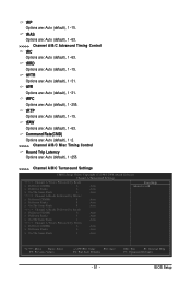
...), 1~31. tFAW Options are : Auto (default), 1~15. tRTP Options are : Auto (default), 1~63. tWTR Options are : Auto (default), 1~15. tRRD Options are : Auto (default), 1~31. BIOS Setup tRAS Options are: Auto (default), 1~63. >>>>> Channel A/B/C Advanced Timing Control tRC Options are: Auto (default), 1~63.
...), 1~31. tFAW Options are : Auto (default), 1~15. tRTP Options are : Auto (default), 1~63. tWTR Options are : Auto (default), 1~15. tRRD Options are : Auto (default), 1~31. BIOS Setup tRAS Options are: Auto (default), 1~63. >>>>> Channel A/B/C Advanced Timing Control tRC Options are: Auto (default), 1~63.
Manual
Page 53
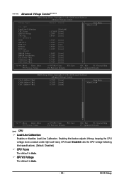
... load. Disabled sets the CPU voltage following Intel specifications. (Default: Disabled) CPU Vcore The default is Auto. - 53 - QPI/Vtt Voltage The default is Auto. BIOS Setup
... load. Disabled sets the CPU voltage following Intel specifications. (Default: Disabled) CPU Vcore The default is Auto. - 53 - QPI/Vtt Voltage The default is Auto. BIOS Setup
Manual
Page 55
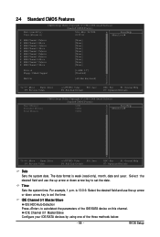
... field and use the up arrow or down arrow key to autodetect the parameters of the three methods below: - 55 - The date format is 13:0:0. BIOS Setup Time Sets the system time.
... field and use the up arrow or down arrow key to autodetect the parameters of the three methods below: - 55 - The date format is 13:0:0. BIOS Setup Time Sets the system time.


