Manual
Page 3
...Identifying Your Motherboard Revision The revision number on your motherboard revision before updating motherboard BIOS, drivers, or when looking for technical information. Check your motherboard looks like this product, GIGABYTE provides the following types of documentations: For quick set-up of ...on how to their respective owners. No part of this manual may be reproduced, copied, translated, transmitted, or published in the use GIGABYTE's unique features, read the User's Manual. For instructions on our website. All rights reserved. For example, "REV: ...
...Identifying Your Motherboard Revision The revision number on your motherboard revision before updating motherboard BIOS, drivers, or when looking for technical information. Check your motherboard looks like this product, GIGABYTE provides the following types of documentations: For quick set-up of ...on how to their respective owners. No part of this manual may be reproduced, copied, translated, transmitted, or published in the use GIGABYTE's unique features, read the User's Manual. For instructions on our website. All rights reserved. For example, "REV: ...
Manual
Page 4
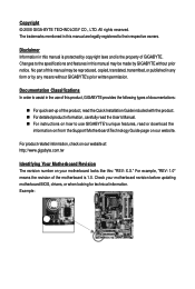
Table of Contents Box Contents ...6 OptionalItems...6 GA-EP45T-UD3LR Motherboard Layout 7 Block Diagram...8 Chapter 1 Hardware Installation 9 1-1 Installation Precautions 9 1-2 Product Specifications 10 1-3 Installing the CPU and CPU Cooler 13...Installing the SATA Bracket 19 1-7 Back Panel Connectors 20 1-8 Internal Connectors 22 Chapter 2 BIOS Setup 33 2-1 Startup Screen 34 2-2 The Main Menu 35 2-3 MB Intelligent Tweaker(M.I.T 37 2-4 Standard CMOS Features 45 2-5 Advanced BIOS Features 47 2-6 IntegratedPeripherals 50 2-7 Power Management Setup 53 2-8 PnP/PCI Configurations 55 ...
Table of Contents Box Contents ...6 OptionalItems...6 GA-EP45T-UD3LR Motherboard Layout 7 Block Diagram...8 Chapter 1 Hardware Installation 9 1-1 Installation Precautions 9 1-2 Product Specifications 10 1-3 Installing the CPU and CPU Cooler 13...Installing the SATA Bracket 19 1-7 Back Panel Connectors 20 1-8 Internal Connectors 22 Chapter 2 BIOS Setup 33 2-1 Startup Screen 34 2-2 The Main Menu 35 2-3 MB Intelligent Tweaker(M.I.T 37 2-4 Standard CMOS Features 45 2-5 Advanced BIOS Features 47 2-6 IntegratedPeripherals 50 2-7 Power Management Setup 53 2-8 PnP/PCI Configurations 55 ...

Manual
Page 5
... 62 3-3 Technical Manuals 62 3-4 Contact ...63 3-5 System ...63 3-6 Download Center 64 Chapter 4 Unique Features 65 4-1 Xpress Recovery2 65 4-2 BIOS Update Utilities 70 4-2-1 Updating the BIOS with the Q-Flash Utility 70 4-2-2 Updating the BIOS with the @BIOS Utility 73 4-3 EasyTune 6 ...74 4-4 Dynamic Energy Saver Advanced 75 4-5 Q-Share ...77 4-6 Time Repair ...78 Chapter 5 Appendix ...79 5-1 Configuring...
... 62 3-3 Technical Manuals 62 3-4 Contact ...63 3-5 System ...63 3-6 Download Center 64 Chapter 4 Unique Features 65 4-1 Xpress Recovery2 65 4-2 BIOS Update Utilities 70 4-2-1 Updating the BIOS with the Q-Flash Utility 70 4-2-2 Updating the BIOS with the @BIOS Utility 73 4-3 EasyTune 6 ...74 4-4 Dynamic Energy Saver Advanced 75 4-5 Q-Share ...77 4-6 Time Repair ...78 Chapter 5 Appendix ...79 5-1 Configuring...

Manual
Page 8
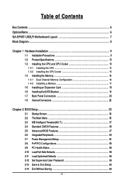
... Interface Intel® P45 DDR3 2200/1600/1333/ 1066/800 MHz Dual Channel Memory MCH CLK (400/333/266/200 MHz) Intel® ICH10R Dual BIOS 6 SATA 3Gb/s 12 USB Ports PCI Bus CODEC LPC Bus IT8718 Floppy LPT Port COM Port PS/2 KB/Mouse Surround Speaker Out Center/Subwoofer Speaker...
... Interface Intel® P45 DDR3 2200/1600/1333/ 1066/800 MHz Dual Channel Memory MCH CLK (400/333/266/200 MHz) Intel® ICH10R Dual BIOS 6 SATA 3Gb/s 12 USB Ports PCI Bus CODEC LPC Bus IT8718 Floppy LPT Port COM Port PS/2 KB/Mouse Surround Speaker Out Center/Subwoofer Speaker...
Manual
Page 12
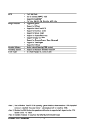
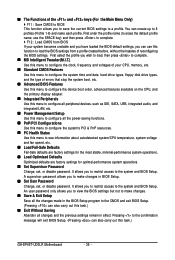
... Software Operating System Form Factor 2 x 8 Mbit flash Use of licensed AWARD BIOS Support for DualBIOSTM PnP 1.0a, DMI 2.0, SM BIOS 2.4, ACPI 1.0b Support for @BIOS Support for Q-Flash Support for Virtual Dual BIOS Support for Download Center Support for Xpress Install Support for Xpress... fan speed control function is supported will depend on the CPU/ System cooler you install. (Note 3) Available functions in EasyTune may differ by motherboard model. GA-EP45T-UD3LR Motherboard - 12 -
... Software Operating System Form Factor 2 x 8 Mbit flash Use of licensed AWARD BIOS Support for DualBIOSTM PnP 1.0a, DMI 2.0, SM BIOS 2.4, ACPI 1.0b Support for @BIOS Support for Q-Flash Support for Virtual Dual BIOS Support for Download Center Support for Xpress Install Support for Xpress... fan speed control function is supported will depend on the CPU/ System cooler you install. (Note 3) Available functions in EasyTune may differ by motherboard model. GA-EP45T-UD3LR Motherboard - 12 -
Manual
Page 16
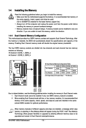
... have a foolproof design. GA-EP45T-UD3LR Motherboard - 16 - When enabling Dual Channel mode with two or four memory modules, it is operating in Flex Memory Mode will double the original memory bandwidth. A memory module can be used . (Go to GIGABYTE's website for optimum performance. After the memory is installed, the BIOS will automatically detect the...
... have a foolproof design. GA-EP45T-UD3LR Motherboard - 16 - When enabling Dual Channel mode with two or four memory modules, it is operating in Flex Memory Mode will double the original memory bandwidth. A memory module can be used . (Go to GIGABYTE's website for optimum performance. After the memory is installed, the BIOS will automatically detect the...
Manual
Page 18
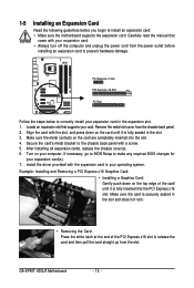
...slot. Align the card with your card. After installing all expansion cards, replace the chassis cover(s). 6. If necessary, go to BIOS Setup to make any required BIOS changes for your computer. Example: Installing and Removing a PCI Express x16 Graphics Card: • Installing a Graphics Card: Gently... card and then pull the card straight up from the chassis back panel. 2. Make sure the metal contacts on your expansion card(s). 7. GA-EP45T-UD3LR Motherboard - 18 - Turn on the card are completely inserted into the PCI Express x16 slot. Install the driver provided with a screw. ...
...slot. Align the card with your card. After installing all expansion cards, replace the chassis cover(s). 6. If necessary, go to BIOS Setup to make any required BIOS changes for your computer. Example: Installing and Removing a PCI Express x16 Graphics Card: • Installing a Graphics Card: Gently... card and then pull the card straight up from the chassis back panel. 2. Make sure the metal contacts on your expansion card(s). 7. GA-EP45T-UD3LR Motherboard - 18 - Turn on the card are completely inserted into the PCI Express x16 slot. Install the driver provided with a screw. ...
Manual
Page 27
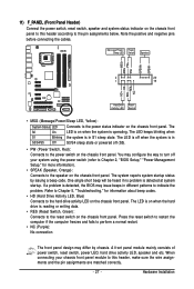
The LED is on when the hard drive is detected, the BIOS may issue beeps in different patterns to indicate the problem. 11) F_PANEL (Front Panel Header) Connect the power switch, reset switch, speaker and system status ... Switch, Green): Connects to the hard drive activity LED on the chassis front panel. When connecting your system using the power switch (refer to Chapter 2, "BIOS Setup," "Power Management Setup," for information about beep codes. • HD (Hard Drive Activity LED, Blue) Connects to the reset switch on the chassis front...
The LED is on when the hard drive is detected, the BIOS may issue beeps in different patterns to indicate the problem. 11) F_PANEL (Front Panel Header) Connect the power switch, reset switch, speaker and system status ... Switch, Green): Connects to the hard drive activity LED on the chassis front panel. When connecting your system using the power switch (refer to Chapter 2, "BIOS Setup," "Power Management Setup," for information about beep codes. • HD (Hard Drive Activity LED, Blue) Connects to the reset switch on the chassis front...
Manual
Page 31
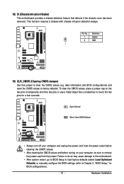
... the two pins to temporarily short the two pins or use a metal object like a screwdriver to Chapter 2, "BIOS Setup," for a few seconds. date information and BIOS configurations) and reset the CMOS values to clear the CMOS values (e.g. To clear the CMOS values, place a jumper...so may cause damage to the motherboard. • After system restart, go to BIOS Setup to load factory defaults (select Load Optimized Defaults) or manually configure the BIOS settings (refer to touch the two pins for BIOS configurations). - 31 - Definition 1 Signal 2 GND 1 19) CLR_CMOS (Clearing ...
... the two pins to temporarily short the two pins or use a metal object like a screwdriver to Chapter 2, "BIOS Setup," for a few seconds. date information and BIOS configurations) and reset the CMOS values to clear the CMOS values (e.g. To clear the CMOS values, place a jumper...so may cause damage to the motherboard. • After system restart, go to BIOS Setup to load factory defaults (select Load Optimized Defaults) or manually configure the BIOS settings (refer to touch the two pins for BIOS configurations). - 31 - Definition 1 Signal 2 GND 1 19) CLR_CMOS (Clearing ...
Manual
Page 32
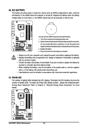
... negative side (-) of the battery (the positive side should face up). • Used batteries must be lost. GA-EP45T-UD3LR Motherboard - 32 - 20) BAT (BATTERY) The battery provides power to keep the values (such as BIOS configurations, date, and time information) in the CMOS when the computer is replaced with an incorrect model. •...
... negative side (-) of the battery (the positive side should face up). • Used batteries must be lost. GA-EP45T-UD3LR Motherboard - 32 - 20) BAT (BATTERY) The battery provides power to keep the values (such as BIOS configurations, date, and time information) in the CMOS when the computer is replaced with an incorrect model. •...
Manual
Page 33
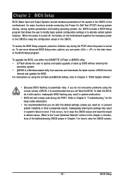
...of the battery/clearing CMOS jumper in this chapter or introductions of BIOS from the Internet and updates the BIOS. BIOS Setup Inadequate BIOS flashing may result in the CMOS. To upgrade the BIOS, use either the GIGABYTE Q-Flash or @BIOS utility. • Q-Flash allows the user to clear the CMOS... values.) - 33 - To see more advanced BIOS Setup menu options, you...
...of the battery/clearing CMOS jumper in this chapter or introductions of BIOS from the Internet and updates the BIOS. BIOS Setup Inadequate BIOS flashing may result in the CMOS. To upgrade the BIOS, use either the GIGABYTE Q-Flash or @BIOS utility. • Q-Flash allows the user to clear the CMOS... values.) - 33 - To see more advanced BIOS Setup menu options, you...
Manual
Page 34
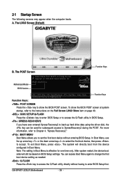
... Screen (Default) Function Keys B. GA-EP45T-UD3LR Motherboard - 34 - For more information, refer to Chapter 4, "Xpress Recovery2." : BOOT MENU Boot Menu allows you have ever entered Xpress Recovery2 to back up arrow key < > or the down arrow key< > to select the first boot device, then press to show the BIOS POST screen at system...
... Screen (Default) Function Keys B. GA-EP45T-UD3LR Motherboard - 34 - For more information, refer to Chapter 4, "Xpress Recovery2." : BOOT MENU Boot Menu allows you have ever entered Xpress Recovery2 to back up arrow key < > or the down arrow key< > to select the first boot device, then press to show the BIOS POST screen at system...
Manual
Page 35
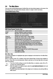
...the current submenus Access the Q-Flash utility Display system information Save all the changes and exit the BIOS Setup program Save CMOS to BIOS Load CMOS from BIOS Change CPU's Clock & Voltage BIOS Setup Program Function Keys Move the selection bar to select an item Execute command or enter the... & Exit Setup Exit Without Saving ESC: Quit F8: Q-Flash Select Item F10: Save & Exit Setup F11: Save CMOS to BIOS F12: Load CMOS from BIOS Main Menu Help The onscreen description of a highlighted setup option is not stable as shown below) appears on the bottom line of ...
...the current submenus Access the Q-Flash utility Display system information Save all the changes and exit the BIOS Setup program Save CMOS to BIOS Load CMOS from BIOS Change CPU's Clock & Voltage BIOS Setup Program Function Keys Move the selection bar to select an item Execute command or enter the... & Exit Setup Exit Without Saving ESC: Quit F8: Q-Flash Select Item F10: Save & Exit Setup F11: Save CMOS to BIOS F12: Load CMOS from BIOS Main Menu Help The onscreen description of a highlighted setup option is not stable as shown below) appears on the bottom line of ...
Manual
Page 36
... this task.) GA-EP45T-UD3LR Motherboard - 36 - A supervisor password allows you can also carry out this task.) Exit Without Saving Abandon all the power-saving functions. PnP/PCI Configurations Use this menu to configure the system's PCI & PnP resources. PC Health Status Use this function to load the BIOS settings from...
... this task.) GA-EP45T-UD3LR Motherboard - 36 - A supervisor password allows you can also carry out this task.) Exit Without Saving Abandon all the power-saving functions. PnP/PCI Configurations Use this menu to configure the system's PCI & PnP resources. PC Health Status Use this function to load the BIOS settings from...
Manual
Page 37
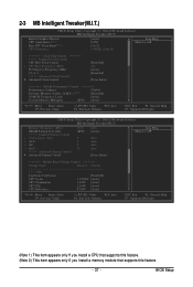
BIOS Setup 2-3 MB Intelligent Tweaker(M.I.T.) CMOS Setup Utility-Copyright (C) 1984-2008 Award Software MB Intelligent Tweaker(M.I.T.) Robust Graphics Booster CPU Clock Ratio (Note 1) Fine CPU Clock ...
BIOS Setup 2-3 MB Intelligent Tweaker(M.I.T.) CMOS Setup Utility-Copyright (C) 1984-2008 Award Software MB Intelligent Tweaker(M.I.T.) Robust Graphics Booster CPU Clock Ratio (Note 1) Fine CPU Clock ...
Manual
Page 38
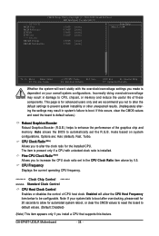
Auto allows the BIOS to automatically set in system's failure to boot. CPU Frequency Displays the current operating CPU frequency. ******** Clock Chip Control Standard Clock Control CPU Host Clock ... configurations. If this feature. Options are: Auto (default), Fast, Turbo. Fine CPU Clock Ratio (Note) Allows you to increase the CPU clock ratio set the R.G.B. GA-EP45T-UD3LR Motherboard - 38 - >>> MCH/ICH MCH Core MCH Reference ICH I/O ICH Core >>> DRAM DRAM Voltage DRAM Termination CMOS Setup Utility-Copyright (C) 1984-2008 Award Software MB...
Auto allows the BIOS to automatically set in system's failure to boot. CPU Frequency Displays the current operating CPU frequency. ******** Clock Chip Control Standard Clock Control CPU Host Clock ... configurations. If this feature. Options are: Auto (default), Fast, Turbo. Fine CPU Clock Ratio (Note) Allows you to increase the CPU clock ratio set the R.G.B. GA-EP45T-UD3LR Motherboard - 38 - >>> MCH/ICH MCH Core MCH Reference ICH I/O ICH Core >>> DRAM DRAM Voltage DRAM Termination CMOS Setup Utility-Copyright (C) 1984-2008 Award Software MB...

Manual
Page 39
...; Move Enter: Select F5: Previous Values +/-/PU/PD: Value F10: Save F6: Fail-Safe Defaults ESC: Exit F1: General Help F7: Optimized Defaults - 39 - BIOS Setup For a 1333 MHz FSB CPU, set this item to 400 MHz. For a 1600 MHz FSB CPU, set this item to 333 MHz. Disabled Disables...
...; Move Enter: Select F5: Previous Values +/-/PU/PD: Value F10: Save F6: Fail-Safe Defaults ESC: Exit F1: General Help F7: Optimized Defaults - 39 - BIOS Setup For a 1333 MHz FSB CPU, set this item to 400 MHz. For a 1600 MHz FSB CPU, set this item to 333 MHz. Disabled Disables...
Manual
Page 40
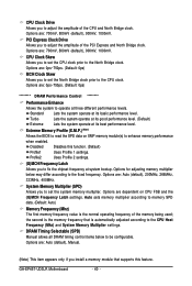
... bootup. Extreme Memory Profile (X.M.P.) (Note) Allows the BIOS to read the SPD data on CPU FSB and the (G)MCH Frequency Latch settings. System Memory Multiplier (SPD) Allows you to enhance memory performance when enabled. the second is the memory frequency that supports this function. (Default) Profile1 Uses Profile 1 settings. GA-EP45T-UD3LR Motherboard - 40 -
... bootup. Extreme Memory Profile (X.M.P.) (Note) Allows the BIOS to read the SPD data on CPU FSB and the (G)MCH Frequency Latch settings. System Memory Multiplier (SPD) Allows you to enhance memory performance when enabled. the second is the memory frequency that supports this function. (Default) Profile1 Uses Profile 1 settings. GA-EP45T-UD3LR Motherboard - 40 -

Manual
Page 41
tRP Options are : Auto (default), 1~15. BIOS Setup tRCD Options are : Auto (default), 1~15. Command Rate(CMD) Options are : Auto (default), 1~31. tWR Options are : Auto (default), 1~3. ******** ESC: Exit F1: General Help ...
tRP Options are : Auto (default), 1~15. BIOS Setup tRCD Options are : Auto (default), 1~15. Command Rate(CMD) Options are : Auto (default), 1~31. tWR Options are : Auto (default), 1~3. ******** ESC: Exit F1: General Help ...
Manual
Page 43
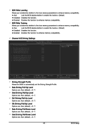
...F1: General Help F7: Optimized Defaults Driving Strength Profile Allows the BIOS to enhance memory compatibility. Cmd Driving Pull-Up Level Options are : Auto (default), +8~-7. - 43 - Auto Lets the BIOS decide whether to enable this function. (Default) Disabled Disables this ...function to enhance memory compatibility. Auto Lets the BIOS decide whether to enable this function. (Default) Disabled Disables this function to...
...F1: General Help F7: Optimized Defaults Driving Strength Profile Allows the BIOS to enhance memory compatibility. Cmd Driving Pull-Up Level Options are : Auto (default), +8~-7. - 43 - Auto Lets the BIOS decide whether to enable this function. (Default) Disabled Disables this ...function to enhance memory compatibility. Auto Lets the BIOS decide whether to enable this function. (Default) Disabled Disables this function to...


