Manual
Page 1
GA-EP45-UD3LR/ GA-EP45-UD3L LGA775 socket motherboard for Intel® CoreTM processor family/ Intel® Pentium® processor family/Intel® Celeron® processor family User's Manual Rev. 1101 12ME-EP45UD3L-1101R
GA-EP45-UD3LR/ GA-EP45-UD3L LGA775 socket motherboard for Intel® CoreTM processor family/ Intel® Pentium® processor family/Intel® Celeron® processor family User's Manual Rev. 1101 12ME-EP45UD3L-1101R
Manual
Page 2
Motherboard GA-EP45-UD3LR/GA-EP45-UD3L Oct. 8, 2008 Motherboard GA-EP45-UD3LR/ GA-EP45-UD3L Oct. 8, 2008
Motherboard GA-EP45-UD3LR/GA-EP45-UD3L Oct. 8, 2008 Motherboard GA-EP45-UD3LR/ GA-EP45-UD3L Oct. 8, 2008
Manual
Page 3
...61550; For instructions on our website. Copyright © 2008 GIGA-BYTE TECHNOLOGY CO., LTD. Disclaimer Information in this manual is protected by GIGABYTE without GIGABYTE's prior written permission. No part of this : "REV: X.X." Documentation Classifications In order to assist in this manual may be made by... manual may be reproduced, copied, translated, transmitted, or published in this manual are legally registered to use GIGABYTE's unique features, read or download the information on/from the Support\Motherboard\Technology Guide page on how to their respective owners.
...61550; For instructions on our website. Copyright © 2008 GIGA-BYTE TECHNOLOGY CO., LTD. Disclaimer Information in this manual is protected by GIGABYTE without GIGABYTE's prior written permission. No part of this : "REV: X.X." Documentation Classifications In order to assist in this manual may be made by... manual may be reproduced, copied, translated, transmitted, or published in this manual are legally registered to use GIGABYTE's unique features, read or download the information on/from the Support\Motherboard\Technology Guide page on how to their respective owners.

Manual
Page 4
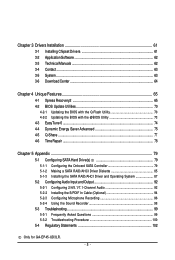
Table of Contents Box Contents ...6 OptionalItems...6 GA-EP45-UD3LR/GA-EP45-UD3L Motherboard Layout 7 Block Diagram...8 Chapter 1 Hardware Installation 9 1-1 Installation Precautions 9 1-2 Product Specifications 10 1-3 Installing the CPU and CPU Cooler 13 1-3-1 Installing the CPU 13 1-3-2 Installing ...
Table of Contents Box Contents ...6 OptionalItems...6 GA-EP45-UD3LR/GA-EP45-UD3L Motherboard Layout 7 Block Diagram...8 Chapter 1 Hardware Installation 9 1-1 Installation Precautions 9 1-2 Product Specifications 10 1-3 Installing the CPU and CPU Cooler 13 1-3-1 Installing the CPU 13 1-3-2 Installing ...
Manual
Page 5
... (Optional 94 5-2-3 Configuring Microphone Recording 96 5-2-4 Using the Sound Recorder 98 5-3 Troubleshooting 99 5-3-1 Frequently Asked Questions 99 5-3-2 Troubleshooting Procedure 100 5-4 Regulatory Statements 102 Only for GA-EP45-UD3LR. - 5 -
... (Optional 94 5-2-3 Configuring Microphone Recording 96 5-2-4 Using the Sound Recorder 98 5-3 Troubleshooting 99 5-3-1 Frequently Asked Questions 99 5-3-2 Troubleshooting Procedure 100 5-4 Regulatory Statements 102 Only for GA-EP45-UD3LR. - 5 -
Manual
Page 6
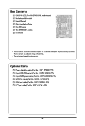
...-2SERPW-0*R) S/PDIF in cable (Part No. 12CR1-1SPDIN-0*R) COM port cable (Part No. 12CF1-1CM001-3*R) LPT port cable (Part No. 12CF1-1LP001-0*R) - 6 - Box Contents GA-EP45-UD3LR or GA-EP45-UD3L motherboard Motherboard driver disk User's Manual Quick Installation Guide One IDE cable Two SATA 3Gb/s cables I/O Shield • The box contents above are subject...
...-2SERPW-0*R) S/PDIF in cable (Part No. 12CR1-1SPDIN-0*R) COM port cable (Part No. 12CF1-1CM001-3*R) LPT port cable (Part No. 12CF1-1LP001-0*R) - 6 - Box Contents GA-EP45-UD3LR or GA-EP45-UD3L motherboard Motherboard driver disk User's Manual Quick Installation Guide One IDE cable Two SATA 3Gb/s cables I/O Shield • The box contents above are subject...
Manual
Page 7
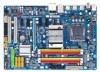
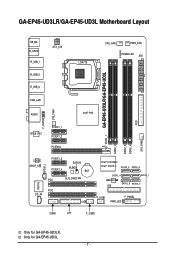
Only for GA-EP45-UD3LR. GA-EP45-UD3LR/GA-EP45-UD3L Motherboard Layout KB_MS R_SPDIF R_USB_1 R_USB_2 R_USB_3 ATX_12V LGA775 CPU_FAN PWR_FAN PHASE LED ATX DDR2_1 GA-EP45-UD3LR/GA-EP45-UD3L DDR2_2 DDR2_3 DDR2_4 FDD SYS_FAN2 USB_LAN F_AUDIO SYS_FAN1 AUDIO Intel® P45 RTL8111C PCIEX1_1 PCIEX1_2 PCIEX16 CODEC SPDIF_O SPDIF_I PCIEX1_3 PCIEX1_4 B_BIOS M_BIOS BAT ... CD_IN CI Intel® ICH10R Intel® ICH10 SATA2_3 SATA2_0 SATA2_4 SATA2_ 1 JMicron 368 IDE SATA2_5 SATA2_2 F_USB1 F_PANEL PWR_LED COMA LPT F_USB2 Only for GA-EP45-UD3L. - 7 -
Only for GA-EP45-UD3LR. GA-EP45-UD3LR/GA-EP45-UD3L Motherboard Layout KB_MS R_SPDIF R_USB_1 R_USB_2 R_USB_3 ATX_12V LGA775 CPU_FAN PWR_FAN PHASE LED ATX DDR2_1 GA-EP45-UD3LR/GA-EP45-UD3L DDR2_2 DDR2_3 DDR2_4 FDD SYS_FAN2 USB_LAN F_AUDIO SYS_FAN1 AUDIO Intel® P45 RTL8111C PCIEX1_1 PCIEX1_2 PCIEX16 CODEC SPDIF_O SPDIF_I PCIEX1_3 PCIEX1_4 B_BIOS M_BIOS BAT ... CD_IN CI Intel® ICH10R Intel® ICH10 SATA2_3 SATA2_0 SATA2_4 SATA2_ 1 JMicron 368 IDE SATA2_5 SATA2_2 F_USB1 F_PANEL PWR_LED COMA LPT F_USB2 Only for GA-EP45-UD3L. - 7 -
Manual
Page 8
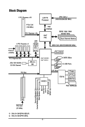
Only for GA-EP45-UD3LR. Block Diagram 1 PCI Express x16 LGA775 Processor CPU CLK+/(400/333/266/200 MHz) PCIe CLK (100 MHz) PCI Express x16 PCIe CLK (100 MHz) 4 ... Speaker Out Center/Subwoofer Speaker Out Side Speaker Out MIC Line-Out Line-In SPDIF In SPDIF Out 2 PCI PCI CLK (33 MHz) Only for GA-EP45-UD3L. - 8 -
Only for GA-EP45-UD3LR. Block Diagram 1 PCI Express x16 LGA775 Processor CPU CLK+/(400/333/266/200 MHz) PCIe CLK (100 MHz) PCI Express x16 PCIe CLK (100 MHz) 4 ... Speaker Out Center/Subwoofer Speaker Out Side Speaker Out MIC Line-Out Line-In SPDIF In SPDIF Out 2 PCI PCI CLK (33 MHz) Only for GA-EP45-UD3L. - 8 -
Manual
Page 9
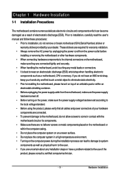
If you are connected tightly and securely. • When handling the motherboard, avoid touching any installation steps or have a problem related to the user. • If you do not have it on top of an antistatic pad or within an electrostatic shielding container. • Before unplugging the power supply cable from the power outlet before installing or removing the motherboard or other hardware components. • When connecting hardware components to the internal connectors on the motherboard, make sure the power supply voltage has been set according to the local voltage standard...
If you are connected tightly and securely. • When handling the motherboard, avoid touching any installation steps or have a problem related to the user. • If you do not have it on top of an antistatic pad or within an electrostatic shielding container. • Before unplugging the power supply cable from the power outlet before installing or removing the motherboard or other hardware components. • When connecting hardware components to the internal connectors on the motherboard, make sure the power supply voltage has been set according to the local voltage standard...

Manual
Page 10
...; Support for DDR2 1366/1066/800/667 MHz memory modules (Go to GIGABYTE's website for the latest memory support list.) Realtek ALC888 codec High Definition Audio 2/4/5.1/7.1-channel Support for S/PDIF In/Out Support for GA-EP45-UD3L. GA-EP45-UD3LR/UD3L Motherboard - 10 - Support for SATA RAID 0, RAID 1, RAID 5 and RAID...
...; Support for DDR2 1366/1066/800/667 MHz memory modules (Go to GIGABYTE's website for the latest memory support list.) Realtek ALC888 codec High Definition Audio 2/4/5.1/7.1-channel Support for S/PDIF In/Out Support for GA-EP45-UD3L. GA-EP45-UD3LR/UD3L Motherboard - 10 - Support for SATA RAID 0, RAID 1, RAID 5 and RAID...
Manual
Page 11
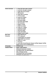
Internal Connectors 1 x 24-pin ATX main power connector 1 x 4-pin ATX 12V power connector 1 x floppy disk drive connector 1 x IDE connector 6 x SATA 3Gb/s connectors 1 x CPU fan header 2 x system fan headers 1 x power fan header 1 x front panel header 1 x front panel audio header 1 x CD In connector 1 x S/PDIF In header 1 x S/PDIF Out header 2 x USB 2.0/1.1 headers 1 x parallel port header 1 x serial port header 1 x power LED ...
Internal Connectors 1 x 24-pin ATX main power connector 1 x 4-pin ATX 12V power connector 1 x floppy disk drive connector 1 x IDE connector 6 x SATA 3Gb/s connectors 1 x CPU fan header 2 x system fan headers 1 x power fan header 1 x front panel header 1 x front panel audio header 1 x CD In connector 1 x S/PDIF In header 1 x S/PDIF Out header 2 x USB 2.0/1.1 headers 1 x parallel port header 1 x serial port header 1 x power LED ...
Manual
Page 12
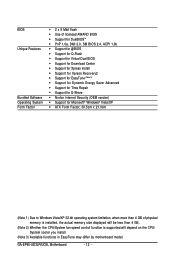
... fan speed control function is supported will depend on the CPU/ System cooler you install. (Note 3) Available functions in EasyTune may differ by motherboard model. GA-EP45-UD3LR/UD3L Motherboard - 12 -
... fan speed control function is supported will depend on the CPU/ System cooler you install. (Note 3) Available functions in EasyTune may differ by motherboard model. GA-EP45-UD3LR/UD3L Motherboard - 12 -
Manual
Page 13
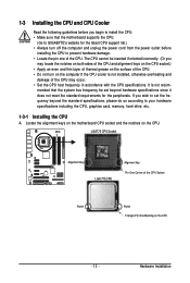
mended that the motherboard supports the CPU. (Go to GIGABYTE's website for the peripherals. Locate the alignment keys on the motherboard CPU socket and the notches on the CPU - 13 - It is not installed, otherwise ...
mended that the motherboard supports the CPU. (Go to GIGABYTE's website for the peripherals. Locate the alignment keys on the motherboard CPU socket and the notches on the CPU - 13 - It is not installed, otherwise ...

Manual
Page 14
... one marking (triangle) with the pin one corner of the CPU socket (or you may align the CPU notches with your thumb and index fingers. B. GA-EP45-UD3LR/UD3L Motherboard - 14 - Before installing the CPU, make sure to correctly install the CPU into the motherboard CPU socket. Step 5: Once the CPU is not...
... one marking (triangle) with the pin one corner of the CPU socket (or you may align the CPU notches with your thumb and index fingers. B. GA-EP45-UD3LR/UD3L Motherboard - 14 - Before installing the CPU, make sure to correctly install the CPU into the motherboard CPU socket. Step 5: Once the CPU is not...
Manual
Page 15
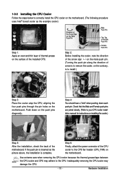
Step 4: You should hear a "click" when pushing down on the push pins diagonally. Use extreme care when removing the CPU cooler because the thermal grease/tape between the CPU cooler and CPU may damage the CPU. - 15 - Inadequately removing the CPU cooler may adhere to install.) Step 3: Place the cooler atop the CPU, aligning the four push pins through the pin holes on the motherboard. Hardware Installation Direction of the Arrow Sign on the Male Push Pin Male Push Pin The Top of Female Push Pin Female Push Pin Step 2: Before installing the cooler, note the direction of the arrow sign ...
Step 4: You should hear a "click" when pushing down on the push pins diagonally. Use extreme care when removing the CPU cooler because the thermal grease/tape between the CPU cooler and CPU may damage the CPU. - 15 - Inadequately removing the CPU cooler may adhere to install.) Step 3: Place the cooler atop the CPU, aligning the four push pins through the pin holes on the motherboard. Hardware Installation Direction of the Arrow Sign on the Male Push Pin Male Push Pin The Top of Female Push Pin Female Push Pin Step 2: Before installing the cooler, note the direction of the arrow sign ...
Manual
Page 16
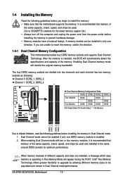
... installed in only one DDR2 memory module is recommended that memory of the same capacity, brand, speed, and chips be used . (Go to GIGABYTE's website for optimum performance. GA-EP45-UD3LR/UD3L Motherboard - 16 - Dual Channel mode cannot be enabled if only one direction. When enabling Dual Channel mode with two or four memory...
... installed in only one DDR2 memory module is recommended that memory of the same capacity, brand, speed, and chips be used . (Go to GIGABYTE's website for optimum performance. GA-EP45-UD3LR/UD3L Motherboard - 16 - Dual Channel mode cannot be enabled if only one direction. When enabling Dual Channel mode with two or four memory...
Manual
Page 17
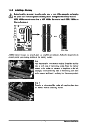
Place the memory module on this motherboard. 1-4-2 Installing a Memory Before installing a memory module , make sure to turn off the computer and unplug the power cord from the power outlet to prevent damage to correctly install your fingers on the top edge of the memory socket. Notch DDR2 DIMM A DDR2 memory module has a notch, so it vertically into place when the memory module is securely inserted. - 17 - Spread the retaining clips at both ends of the memory, push down on the memory and insert it can only fit in the picture on the left, place your memory modules in the...
Place the memory module on this motherboard. 1-4-2 Installing a Memory Before installing a memory module , make sure to turn off the computer and unplug the power cord from the power outlet to prevent damage to correctly install your fingers on the top edge of the memory socket. Notch DDR2 DIMM A DDR2 memory module has a notch, so it vertically into place when the memory module is securely inserted. - 17 - Spread the retaining clips at both ends of the memory, push down on the memory and insert it can only fit in the picture on the left, place your memory modules in the...

Manual
Page 18
... expansion card in your card. PCI Express x1 Slot PCI Express x16 Slot PCI Slot Follow the steps below to correctly install your expansion card(s). 7. GA-EP45-UD3LR/UD3L Motherboard - 18 - After installing all expansion cards, replace the chassis cover(s). 6. Install the driver provided with a screw. 5. Make sure the card is fully inserted...
... expansion card in your card. PCI Express x1 Slot PCI Express x16 Slot PCI Slot Follow the steps below to correctly install your expansion card(s). 7. GA-EP45-UD3LR/UD3L Motherboard - 18 - After installing all expansion cards, replace the chassis cover(s). 6. Install the driver provided with a screw. 5. Make sure the card is fully inserted...
Manual
Page 19
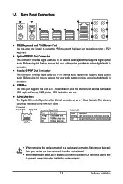
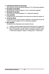
1-6 Back Panel Connectors PS/2 Keyboard and PS/2 Mouse Port Use the upper port (green) to connect a PS/2 mouse and the lower port (purple) to 1 Gbps data rate. Before using this feature, ensure that supports digital optical audio. USB Port The USB port supports the USB 2.0/1.1 specification. RJ-45 LAN Port The Gigabit Ethernet LAN port provides Internet connection at up to connect a PS/2 keyboard. Hardware Installation Use this feature, ensure that supports digital coaxial audio. Coaxial S/PDIF Out Connector This connector provides digital audio out to a back panel ...
1-6 Back Panel Connectors PS/2 Keyboard and PS/2 Mouse Port Use the upper port (green) to connect a PS/2 mouse and the lower port (purple) to 1 Gbps data rate. Before using this feature, ensure that supports digital optical audio. USB Port The USB port supports the USB 2.0/1.1 specification. RJ-45 LAN Port The Gigabit Ethernet LAN port provides Internet connection at up to connect a PS/2 keyboard. Hardware Installation Use this feature, ensure that supports digital coaxial audio. Coaxial S/PDIF Out Connector This connector provides digital audio out to a back panel ...
Manual
Page 20
... default Mic in devices such as an optical drive, walkman, etc. Only microphones still MUST be reconfigured to perform different functions via the audio software. GA-EP45-UD3LR/UD3L Motherboard - 20 - Line Out Jack (Green) The default line out jack. This jack can be connected to the default Mic in a 4/5.1/7.1-channel audio configuration...
... default Mic in devices such as an optical drive, walkman, etc. Only microphones still MUST be reconfigured to perform different functions via the audio software. GA-EP45-UD3LR/UD3L Motherboard - 20 - Line Out Jack (Green) The default line out jack. This jack can be connected to the default Mic in a 4/5.1/7.1-channel audio configuration...