Manual
Page 4
Table of Contents Box Contents ...6 OptionalItems ...6 GA-EP45-DS3R/DS3 Motherboard Layout 7 Block Diagram ...8 Chapter 1 Hardware Installation 9 1-1 Installation Precautions 9 1-2 Product Specifications 10 1-3 Installing the CPU and CPU Cooler 13 1-3-1 Installing the CPU 13 1-3-2 Installing the ... 60 2-12 Set Supervisor/User Password 61 2-13 Save & Exit Setup 62 2-14 Exit Without Saving 62 2-15 Security Chip Configuration (Note 63 Only for GA-EP45-DS3R. - 4 -
Table of Contents Box Contents ...6 OptionalItems ...6 GA-EP45-DS3R/DS3 Motherboard Layout 7 Block Diagram ...8 Chapter 1 Hardware Installation 9 1-1 Installation Precautions 9 1-2 Product Specifications 10 1-3 Installing the CPU and CPU Cooler 13 1-3-1 Installing the CPU 13 1-3-2 Installing the ... 60 2-12 Set Supervisor/User Password 61 2-13 Save & Exit Setup 62 2-14 Exit Without Saving 62 2-15 Security Chip Configuration (Note 63 Only for GA-EP45-DS3R. - 4 -
Manual
Page 7
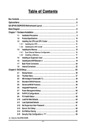
Only for GA-EP45-DS3R. GA-EP45-DS3R/DS3 Motherboard Layout KB_MS R_SPDIF ATX_12V_2X4 USB_1394_2 USB_1394_1 USB_LAN2 LGA775 CPU_FAN PHASE LED ATX GA-EP45-DS3R/DS3 USB_LAN1 RTL8111C FDD AUDIO F_AUDIO Intel® P45 SYS_FAN1 PCIEX1_1 RTL8111C PCIEX16_1 PCIEX1_2 CODEC PCIEX1_3 SPDIF_I SPDIF_O PCIEX8_1 PCI1 DDR2_1 DDR2_2 DDR2_3 CLR_CMOS... TPM IC (Note) F_USB2 F_USB1 IT8718 PCI2 CD_IN CI SATA2_4 SATA2_2 SATA2_0 SATA2_5 SATA2_3 SATA2_1 COMA LPT F_PANEL F1_1394 PWR_LED Only for GA-EP45-DS3. (Note) This feature is optional due to different regional policy. - 7 -
Only for GA-EP45-DS3R. GA-EP45-DS3R/DS3 Motherboard Layout KB_MS R_SPDIF ATX_12V_2X4 USB_1394_2 USB_1394_1 USB_LAN2 LGA775 CPU_FAN PHASE LED ATX GA-EP45-DS3R/DS3 USB_LAN1 RTL8111C FDD AUDIO F_AUDIO Intel® P45 SYS_FAN1 PCIEX1_1 RTL8111C PCIEX16_1 PCIEX1_2 CODEC PCIEX1_3 SPDIF_I SPDIF_O PCIEX8_1 PCI1 DDR2_1 DDR2_2 DDR2_3 CLR_CMOS... TPM IC (Note) F_USB2 F_USB1 IT8718 PCI2 CD_IN CI SATA2_4 SATA2_2 SATA2_0 SATA2_5 SATA2_3 SATA2_1 COMA LPT F_PANEL F1_1394 PWR_LED Only for GA-EP45-DS3. (Note) This feature is optional due to different regional policy. - 7 -
Manual
Page 10
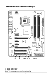
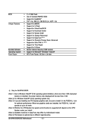
...x1 slots Š 2 x PCI slots Š South Bridge: - 6 x SATA 3Gb/s connectors supporting up to 1 floppy disk drive Š T.I. GA-EP45-DS3R/DS3 Motherboard - 10 - 1-2 Product Specifications CPU Front Side Bus Chipset Memory Audio LAN Expansion Slots Storage Interface IEEE 1394 Š Support for an Intel® ...memory (Note 1) Š Dual channel memory architecture Š Support for DDR2 1200/1066/800/667 MHz memory modules (Go to GIGABYTE's website for the latest memory support list.) Š Realtek ALC889A codec Š High Definition Audio Š 2/4/5.1/7.1-channel Š Support...
...x1 slots Š 2 x PCI slots Š South Bridge: - 6 x SATA 3Gb/s connectors supporting up to 1 floppy disk drive Š T.I. GA-EP45-DS3R/DS3 Motherboard - 10 - 1-2 Product Specifications CPU Front Side Bus Chipset Memory Audio LAN Expansion Slots Storage Interface IEEE 1394 Š Support for an Intel® ...memory (Note 1) Š Dual channel memory architecture Š Support for DDR2 1200/1066/800/667 MHz memory modules (Go to GIGABYTE's website for the latest memory support list.) Š Realtek ALC889A codec Š High Definition Audio Š 2/4/5.1/7.1-channel Š Support...
Manual
Page 12
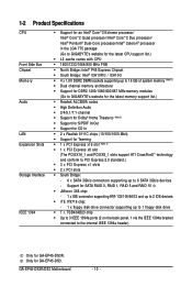
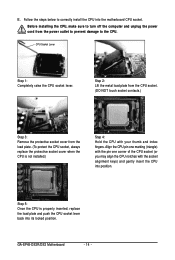
GA-EP45-DS3R/DS3 Motherboard - 12 - When two graphics cards are installed, the PCIEX16_1 slot will operate at up to x8 mode. (Note 4) Whether the CPU/System fan speed ... will depend on the CPU/ System cooler you are installing one PCI Express graphics card, be sure to install it in the PCIEX16_1 slot for GA-EP45-DS3R. (Note 1) Due to Windows Vista/XP 32-bit operating system limitation, when more than 4 GB of physical memory is installed, the actual memory size displayed...
GA-EP45-DS3R/DS3 Motherboard - 12 - When two graphics cards are installed, the PCIEX16_1 slot will operate at up to x8 mode. (Note 4) Whether the CPU/System fan speed ... will depend on the CPU/ System cooler you are installing one PCI Express graphics card, be sure to install it in the PCIEX16_1 slot for GA-EP45-DS3R. (Note 1) Due to Windows Vista/XP 32-bit operating system limitation, when more than 4 GB of physical memory is installed, the actual memory size displayed...
Manual
Page 14
CPU Socket Lever Step 1: Completely raise the CPU socket lever. GA-EP45-DS3R/DS3 Motherboard - 14 - Align the CPU pin one marking (triangle) with the pin one corner of the CPU socket (or you may align the CPU notches ...
CPU Socket Lever Step 1: Completely raise the CPU socket lever. GA-EP45-DS3R/DS3 Motherboard - 14 - Align the CPU pin one marking (triangle) with the pin one corner of the CPU socket (or you may align the CPU notches ...
Manual
Page 16
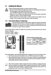
...-Sided, DS=Double-Sided, "- -"=No Memory) DDR2_1 DDR2_2 DDR2_3 DDR2_4 Due to prevent hardware damage. • Memory modules have a foolproof design. GA-EP45-DS3R/DS3 Motherboard - 16 - A memory module can be used . (Go to GIGABYTE's website for optimum performance. DS/SS - - - - It is operating in Dual Channel mode. 1. Enabling Dual Channel memory mode will automatically...
...-Sided, DS=Double-Sided, "- -"=No Memory) DDR2_1 DDR2_2 DDR2_3 DDR2_4 Due to prevent hardware damage. • Memory modules have a foolproof design. GA-EP45-DS3R/DS3 Motherboard - 16 - A memory module can be used . (Go to GIGABYTE's website for optimum performance. DS/SS - - - - It is operating in Dual Channel mode. 1. Enabling Dual Channel memory mode will automatically...
Manual
Page 18
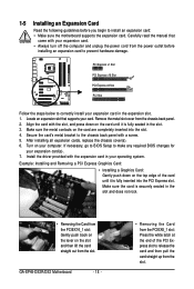
... card straight up from the PCIEX8_1 slot: Press the white latch at the end of the card until it is fully seated in your computer. GA-EP45-DS3R/DS3 Motherboard - 18 - • Removing the Card from the slot. Turn on your operating system. 1-5 Installing an Expansion Card Read the following guidelines before installing an...
... card straight up from the PCIEX8_1 slot: Press the white latch at the end of the card until it is fully seated in your computer. GA-EP45-DS3R/DS3 Motherboard - 18 - • Removing the Card from the slot. Turn on your operating system. 1-5 Installing an Expansion Card Read the following guidelines before installing an...
Manual
Page 20
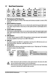
... system that supports digital coaxial audio. Use this port for USB devices such as an USB keyboard/mouse, USB printer, USB flash drive and etc. GA-EP45-DS3R/DS3 Motherboard - 20 - USB Port The USB port supports the USB 2.0/1.1 specification. IEEE 1394a Port The IEEE 1394 port supports the IEEE 1394a specification, featuring high...
... system that supports digital coaxial audio. Use this port for USB devices such as an USB keyboard/mouse, USB printer, USB flash drive and etc. GA-EP45-DS3R/DS3 Motherboard - 20 - USB Port The USB port supports the USB 2.0/1.1 specification. IEEE 1394a Port The IEEE 1394 port supports the IEEE 1394a specification, featuring high...
Manual
Page 22
GA-EP45-DS3R/DS3 Motherboard - 22 - Unplug the power cord from the power outlet to prevent damage to the devices. • After installing the device and before connecting external ...
GA-EP45-DS3R/DS3 Motherboard - 22 - Unplug the power cord from the power outlet to prevent damage to the devices. • After installing the device and before connecting external ...
Manual
Page 24
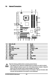
... possess a foolproof insertion design. Overheating may result in the correct orientation (the black connector wire is typically designated by a stripe of different color. 34 33 GA-EP45-DS3R/DS3 Motherboard 2 1 - 24 - When connecting a fan cable, be sure to the CPU or the system may hang. • These fan headers are : 360 KB, 720 KB...
... possess a foolproof insertion design. Overheating may result in the correct orientation (the black connector wire is typically designated by a stripe of different color. 34 33 GA-EP45-DS3R/DS3 Motherboard 2 1 - 24 - When connecting a fan cable, be sure to the CPU or the system may hang. • These fan headers are : 360 KB, 720 KB...
Manual
Page 26
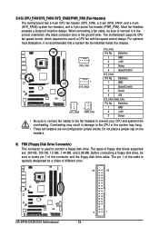
... (S5). Only for instructions on configuring a RAID array. Pin No. 1 2 3 Definition MPD+ MPDMPD- Refer to Chapter 5, "Configuring SATA Hard Drive(s)," for GA-EP45-DS3R. The LED is in S1 sleep state. GA-EP45-DS3R/DS3 Motherboard 1 - 26 - The LED keeps blinking when the system is in S3/S4 sleep state or powered off when the system is...
... (S5). Only for instructions on configuring a RAID array. Pin No. 1 2 3 Definition MPD+ MPDMPD- Refer to Chapter 5, "Configuring SATA Hard Drive(s)," for GA-EP45-DS3R. The LED is in S1 sleep state. GA-EP45-DS3R/DS3 Motherboard 1 - 26 - The LED keeps blinking when the system is in S3/S4 sleep state or powered off when the system is...
Manual
Page 28
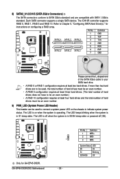
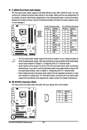
... connection between the module connector and the motherboard header will be present on each wire instead of the motherboard header. Definition 1 CD-L 2 GND 3 GND 4 CD-R 1 GA-EP45-DS3R/DS3 Motherboard - 28 - You may connect the audio cable that has different wire assignments, please contact the chassis manufacturer. 12) CD_IN (CD In Connector, Black) You...
... connection between the module connector and the motherboard header will be present on each wire instead of the motherboard header. Definition 1 CD-L 2 GND 3 GND 4 CD-R 1 GA-EP45-DS3R/DS3 Motherboard - 28 - You may connect the audio cable that has different wire assignments, please contact the chassis manufacturer. 12) CD_IN (CD In Connector, Black) You...
Manual
Page 30
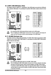
GA-EP45-DS3R/DS3 Motherboard - 30 - Each USB header can provide one end of the device cable to your computer and then attach the other end of the cable ...
GA-EP45-DS3R/DS3 Motherboard - 30 - Each USB header can provide one end of the device cable to your computer and then attach the other end of the cable ...
Manual
Page 32
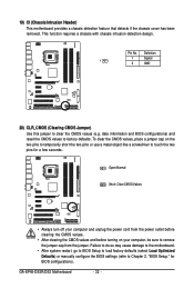
... BIOS settings (refer to touch the two pins for BIOS configurations). Definition 1 Signal 1 2 GND 20) CLR_CMOS (Clearing CMOS Jumper) Use this jumper to factory defaults. GA-EP45-DS3R/DS3 Motherboard - 32 - Open: Normal Short: Clear CMOS Values • Always turn off your computer, be sure to remove the jumper cap from the power outlet...
... BIOS settings (refer to touch the two pins for BIOS configurations). Definition 1 Signal 1 2 GND 20) CLR_CMOS (Clearing CMOS Jumper) Use this jumper to factory defaults. GA-EP45-DS3R/DS3 Motherboard - 32 - Open: Normal Short: Clear CMOS Values • Always turn off your computer, be sure to remove the jumper cap from the power outlet...

Manual
Page 34
GA-EP45-DS3R/DS3 Motherboard - 34 -
GA-EP45-DS3R/DS3 Motherboard - 34 -
Manual
Page 36
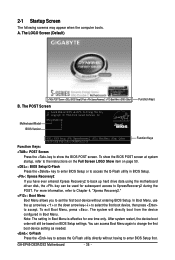
...from the device configured in Boot Menu. The LOGO Screen (Default) :POST Screen :BIOS Setup/Q-Flash :XpressRecovery2 :Boot Menu :Qflash Function Keys B. EP45-DS3R F3l . . . . : BIOS Setup : XpressRecovery2 : Boot Menu : Qflash 05/20/2008-P45-ICH10-7A89PG01C-00 Function Keys Function Keys: ...Copyright (C) 1984-2008, Award Software, Inc. The system will still be used for one time only. To exit Boot Menu, press . GA-EP45-DS3R/DS3 Motherboard - 36 - Note: The setting in BIOS Setup. : Xpress Recovery2 If you to XpressRecovery2 during the POST. You can be based...
...from the device configured in Boot Menu. The LOGO Screen (Default) :POST Screen :BIOS Setup/Q-Flash :XpressRecovery2 :Boot Menu :Qflash Function Keys B. EP45-DS3R F3l . . . . : BIOS Setup : XpressRecovery2 : Boot Menu : Qflash 05/20/2008-P45-ICH10-7A89PG01C-00 Function Keys Function Keys: ...Copyright (C) 1984-2008, Award Software, Inc. The system will still be used for one time only. To exit Boot Menu, press . GA-EP45-DS3R/DS3 Motherboard - 36 - Note: The setting in BIOS Setup. : Xpress Recovery2 If you to XpressRecovery2 during the POST. You can be based...

Manual
Page 38
It allows you to a profile. GA-EP45-DS3R/DS3 Motherboard - 38 - An user password only allows you to save the current BIOS settings to make changes. „ Save & Exit Setup Save all the changes ... Defaults Fail-Safe defaults are factory settings for the most stable, minimal-performance system operations. „ Load Optimized Defaults Optimized defaults are factory settings for GA-EP45-DS3R. First select the profile you to restrict access to configure the TPM function.
It allows you to a profile. GA-EP45-DS3R/DS3 Motherboard - 38 - An user password only allows you to save the current BIOS settings to make changes. „ Save & Exit Setup Save all the changes ... Defaults Fail-Safe defaults are factory settings for the most stable, minimal-performance system operations. „ Load Optimized Defaults Optimized defaults are factory settings for GA-EP45-DS3R. First select the profile you to restrict access to configure the TPM function.

Manual
Page 40
... default values.) Robust Graphics Booster Robust Graphics Booster (R.G.B.) helps to be configurable. Note: If your overall system configurations. This page is dependent on system configurations. GA-EP45-DS3R/DS3 Motherboard - 40 -
... default values.) Robust Graphics Booster Robust Graphics Booster (R.G.B.) helps to be configurable. Note: If your overall system configurations. This page is dependent on system configurations. GA-EP45-DS3R/DS3 Motherboard - 40 -
Manual
Page 42
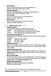
... operate at its best performance level. DRAM Timing Selectable (SPD) Manual allows all DRAM Timing items below may differ according to the North Bridge clock. GA-EP45-DS3R/DS3 Motherboard - 42 - Options are : 0ps~750ps. (Default: 0ps) MCH Clock Skew Allows you to set the CPU clock prior to the fixed frequency. Lets the...
... operate at its best performance level. DRAM Timing Selectable (SPD) Manual allows all DRAM Timing items below may differ according to the North Bridge clock. GA-EP45-DS3R/DS3 Motherboard - 42 - Options are : 0ps~750ps. (Default: 0ps) MCH Clock Skew Allows you to set the CPU clock prior to the fixed frequency. Lets the...

Manual
Page 44
.... tRFC Options are : Auto (default), 0-Normal, 1-Advanced. tRD Phase2 Adjustment Options are : Auto (default), 1~255. ******** Advanced Timing Control ******** tRRD Options are : Auto (default), 0-Normal, 1-Advanced. GA-EP45-DS3R/DS3 Motherboard - 44 - tRD Phase0 Adjustment Options are : Auto (default), 1~15. tWTR Options are: Auto (default), 1~31.
.... tRFC Options are : Auto (default), 0-Normal, 1-Advanced. tRD Phase2 Adjustment Options are : Auto (default), 1~255. ******** Advanced Timing Control ******** tRRD Options are : Auto (default), 0-Normal, 1-Advanced. GA-EP45-DS3R/DS3 Motherboard - 44 - tRD Phase0 Adjustment Options are : Auto (default), 1~15. tWTR Options are: Auto (default), 1~31.


