Manual
Page 3
For instructions on how to the specifications and features in the use GIGABYTE's unique features, read or download the information on/from the Support&Downloads\Motherboard\Technology Guide page on your motherboard revision before updating motherboard BIOS, drivers, or when looking for technical information. Example: For detailed product information, carefully read the Quick...
For instructions on how to the specifications and features in the use GIGABYTE's unique features, read or download the information on/from the Support&Downloads\Motherboard\Technology Guide page on your motherboard revision before updating motherboard BIOS, drivers, or when looking for technical information. Example: For detailed product information, carefully read the Quick...
Manual
Page 4
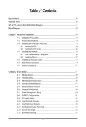
Table of Contents Box Contents...6 Optional Items...6 GA-EP41-UD3L/US3L Motherboard Layout 7 Block Diagram...8 Chapter 1 Hardware Installation 9 1-1 Installation Precautions 9 1-2 Product Specifications 10 1-3 Installing the CPU and CPU ...1-5 Installing an Expansion Card 18 1-6 Back Panel Connectors 19 1-7 Internal Connectors 21 Chapter 2 BIOS Setup 31 2-1 Startup Screen 32 2-2 The Main Menu 33 2-3 MB Intelligent Tweaker(M.I.T 35 2-4 Standard CMOS Features 41 2-5 Advanced BIOS Features 43 2-6 Integrated Peripherals 46 2-7 Power Management Setup 49 2-8 PnP/PCI Configurations 51 ...
Table of Contents Box Contents...6 Optional Items...6 GA-EP41-UD3L/US3L Motherboard Layout 7 Block Diagram...8 Chapter 1 Hardware Installation 9 1-1 Installation Precautions 9 1-2 Product Specifications 10 1-3 Installing the CPU and CPU ...1-5 Installing an Expansion Card 18 1-6 Back Panel Connectors 19 1-7 Internal Connectors 21 Chapter 2 BIOS Setup 31 2-1 Startup Screen 32 2-2 The Main Menu 33 2-3 MB Intelligent Tweaker(M.I.T 35 2-4 Standard CMOS Features 41 2-5 Advanced BIOS Features 43 2-6 Integrated Peripherals 46 2-7 Power Management Setup 49 2-8 PnP/PCI Configurations 51 ...
Manual
Page 5
... 58 3-3 Technical Manuals 58 3-4 Contact...59 3-5 System...59 3-6 Download Center 60 Chapter 4 Unique Features 61 4-1 Xpress Recovery2 61 4-2 BIOS Update Utilities 64 4-2-1 Updating the BIOS with the Q-Flash Utility 64 4-2-2 Updating the BIOS with the @BIOS Utility 67 4-3 EasyTune 6...68 4-4 Dynamic Energy Saver Advanced 69 4-5 Q-Share...71 4-6 Time Repair...72 Chapter 5 Appendix...73 5-1 Configuring...
... 58 3-3 Technical Manuals 58 3-4 Contact...59 3-5 System...59 3-6 Download Center 60 Chapter 4 Unique Features 61 4-1 Xpress Recovery2 61 4-2 BIOS Update Utilities 64 4-2-1 Updating the BIOS with the Q-Flash Utility 64 4-2-2 Updating the BIOS with the @BIOS Utility 67 4-3 EasyTune 6...68 4-4 Dynamic Energy Saver Advanced 69 4-5 Q-Share...71 4-6 Time Repair...72 Chapter 5 Appendix...73 5-1 Configuring...

Manual
Page 8
Block Diagram PCIe CLK (100 MHz) 1 PCI Express x16 PCI Express x16 LAN RJ45 RTL8111C/D(L) x1 PCI Express Bus 3 PCI Express x1 x1 x1 x1 PCIe CLK (100 MHz) PCI Bus LGA775 Processor CPU CLK+/(333/266/200 MHz) Host Interface Intel® G41 DDR2 800/667 MHz Dual Channel Memory GMCH CLK (333/266/200 MHz) Intel® ICH7 CODEC Dual BIOS ATA-100/66/33 IDE Channel 4 SATA 3Gb/s 8 USB Ports IT8718 Floppy LPT Port COM Port PS/2 KB/Mouse Surround Speaker Out Center/Subwoofer Speaker Out Side Speaker Out MIC Line Out Line In S/PDIF In S/ PDIF Out 3 PCI PCI CLK (33 MHz) - 8 -
Block Diagram PCIe CLK (100 MHz) 1 PCI Express x16 PCI Express x16 LAN RJ45 RTL8111C/D(L) x1 PCI Express Bus 3 PCI Express x1 x1 x1 x1 PCIe CLK (100 MHz) PCI Bus LGA775 Processor CPU CLK+/(333/266/200 MHz) Host Interface Intel® G41 DDR2 800/667 MHz Dual Channel Memory GMCH CLK (333/266/200 MHz) Intel® ICH7 CODEC Dual BIOS ATA-100/66/33 IDE Channel 4 SATA 3Gb/s 8 USB Ports IT8718 Floppy LPT Port COM Port PS/2 KB/Mouse Surround Speaker Out Center/Subwoofer Speaker Out Side Speaker Out MIC Line Out Line In S/PDIF In S/ PDIF Out 3 PCI PCI CLK (33 MHz) - 8 -

Manual
Page 12
...Bundled Software Operating System Form Factor w 2 x 8 Mbit flash w Use of licensed AWARD BIOS w Support for DualBIOS™ w PnP 1.0a, DMI 2.0, SM BIOS 2.4, ACPI 1.0b w Support for @BIOS w Support for Q-Flash w Support for Xpress BIOS Rescue w Support for Download Center w Support for Xpress Install w Support for Xpress Recovery2 w..., to avoid the system being unable to start or the memory being incorrectly detected, if only one memory module is to GIGABYTE's website for the latest memory support list.) (Note 3) Whether the CPU/system fan speed control function is supported will depend...
...Bundled Software Operating System Form Factor w 2 x 8 Mbit flash w Use of licensed AWARD BIOS w Support for DualBIOS™ w PnP 1.0a, DMI 2.0, SM BIOS 2.4, ACPI 1.0b w Support for @BIOS w Support for Q-Flash w Support for Xpress BIOS Rescue w Support for Download Center w Support for Xpress Install w Support for Xpress Recovery2 w..., to avoid the system being unable to start or the memory being incorrectly detected, if only one memory module is to GIGABYTE's website for the latest memory support list.) (Note 3) Whether the CPU/system fan speed control function is supported will depend...
Manual
Page 16
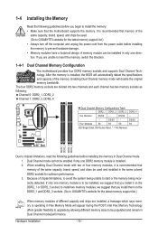
After the memory is installed, the BIOS will automatically detect the specifications and capacity of the same capacity, brand, ...When enabling Dual Channel mode with two or four memory modules, it on the DDR2_1 and DDR2_3 sockets. (Go to GIGABYTE's website for the latest memory support list.) When memory modules of different capacity and chips are installed, a message which ...install it is recommended that memory of the same capacity, brand, speed, and chips be used . (Go to GIGABYTE's website for the latest memory support list.) • Always turn off the computer and unplug the power cord ...
After the memory is installed, the BIOS will automatically detect the specifications and capacity of the same capacity, brand, ...When enabling Dual Channel mode with two or four memory modules, it on the DDR2_1 and DDR2_3 sockets. (Go to GIGABYTE's website for the latest memory support list.) When memory modules of different capacity and chips are installed, a message which ...install it is recommended that memory of the same capacity, brand, speed, and chips be used . (Go to GIGABYTE's website for the latest memory support list.) • Always turn off the computer and unplug the power cord ...
Manual
Page 18
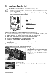
... the card is fully inserted into the slot. 4. 1-5 Installing an Expansion Card Read the following guidelines before installing an expansion card to make any required BIOS changes for your expansion card(s). 7. Carefully read the manual that supports your operating system. Align the card with a screw. 5. Remove the metal slot cover from... an expansion card: • Make sure the motherboard supports the expansion card. After installing all expansion cards, replace the chassis cover(s). 6. If necessary, go to BIOS Setup to prevent hardware damage.
... the card is fully inserted into the slot. 4. 1-5 Installing an Expansion Card Read the following guidelines before installing an expansion card to make any required BIOS changes for your expansion card(s). 7. Carefully read the manual that supports your operating system. Align the card with a screw. 5. Remove the metal slot cover from... an expansion card: • Make sure the motherboard supports the expansion card. After installing all expansion cards, replace the chassis cover(s). 6. If necessary, go to BIOS Setup to prevent hardware damage.
Manual
Page 25
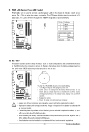
... regulations. - 25 - Danger of explosion if the battery is operating. Replace the battery. 4. The LED is on the chassis to keep the values (such as BIOS configurations, date, and time information) in the CMOS when the computer is turned off (S5).
... regulations. - 25 - Danger of explosion if the battery is operating. Replace the battery. 4. The LED is on the chassis to keep the values (such as BIOS configurations, date, and time information) in the CMOS when the computer is turned off (S5).
Manual
Page 26
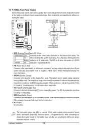
...power switch, reset switch, power LED, hard drive activity LED, speaker and etc. When connecting your system using the power switch (refer to Chapter 2, "BIOS Setup," "Power Management Setup," for information about beep codes. • HD (Hard Drive Activity LED, Blue) Connects to the power switch on the ...Speaker MSG+ MSG- PW+ PWSPEAK+ SPEAK- 2 20 1 19 HD+ HD- The LED keeps blinking when the S1 Blinking system is detected, the BIOS may configure the way to turn off (S5). • PW (Power Switch, Red): Connects to the hard drive activity LED on the chassis front panel...
...power switch, reset switch, power LED, hard drive activity LED, speaker and etc. When connecting your system using the power switch (refer to Chapter 2, "BIOS Setup," "Power Management Setup," for information about beep codes. • HD (Hard Drive Activity LED, Blue) Connects to the power switch on the ...Speaker MSG+ MSG- PW+ PWSPEAK+ SPEAK- 2 20 1 19 HD+ HD- The LED keeps blinking when the S1 Blinking system is detected, the BIOS may configure the way to turn off (S5). • PW (Power Switch, Red): Connects to the hard drive activity LED on the chassis front panel...
Manual
Page 30
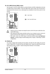
... Failure to do so may cause damage to the motherboard. • After system restart, go to BIOS Setup to load factory defaults (select Load Optimized Defaults) or manually configure the BIOS settings (refer to clear the CMOS values (e.g. 18) CLR_CMOS (Clearing CMOS Jumper) Use this jumper ...to Chapter 2, "BIOS Setup," for BIOS configurations). 19) PHASE LED The number of lighted LEDs. date information and BIOS configurations) and reset the CMOS values to remove the jumper cap from the power outlet before ...
... Failure to do so may cause damage to the motherboard. • After system restart, go to BIOS Setup to load factory defaults (select Load Optimized Defaults) or manually configure the BIOS settings (refer to clear the CMOS values (e.g. 18) CLR_CMOS (Clearing CMOS Jumper) Use this jumper ...to Chapter 2, "BIOS Setup," for BIOS configurations). 19) PHASE LED The number of lighted LEDs. date information and BIOS configurations) and reset the CMOS values to remove the jumper cap from the power outlet before ...
Manual
Page 31
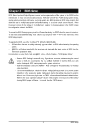
... the configuration values in the CMOS. To upgrade the BIOS, use either the GIGABYTE Q-Flash or @BIOS utility. • Q-Flash allows the user to quickly and easily upgrade or back up BIOS without entering the operating system. • @BIOS is a Windows-based utility that searches and downloads the... latest version of the BIOS Setup program. If this occurs, try...
... the configuration values in the CMOS. To upgrade the BIOS, use either the GIGABYTE Q-Flash or @BIOS utility. • Q-Flash allows the user to quickly and easily upgrade or back up BIOS without entering the operating system. • @BIOS is a Windows-based utility that searches and downloads the... latest version of the BIOS Setup program. If this occurs, try...

Manual
Page 32
... Boot Menu again to change the first boot device setting as needed. : Q-FLASH Press the key to accept. The LOGO Screen (Default) B. Motherboard Model BIOS Version EP41-UD3L F2e . . . . : BIOS Setup : XpressRecovery2 : Boot Menu : Qflash 03/11/2009-G41-ICH7-7A69PG0OC-00 Function Keys Function Keys Function Keys: : POST SCREEN Press the key to...
... Boot Menu again to change the first boot device setting as needed. : Q-FLASH Press the key to accept. The LOGO Screen (Default) B. Motherboard Model BIOS Version EP41-UD3L F2e . . . . : BIOS Setup : XpressRecovery2 : Boot Menu : Qflash 03/11/2009-G41-ICH7-7A69PG0OC-00 Function Keys Function Keys Function Keys: : POST SCREEN Press the key to...
Manual
Page 33
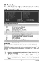
...the screen. Use arrow keys to move among the items and press to accept or enter a sub-menu. (Sample BIOS Version: GA-EP41-UD3L F2e) CMOS Setup Utility-Copyright (C) 1984-2009 Award Software MB Intelligent Tweaker(M.I.T.) Standard CMOS Features Advanced... BIOS Features Integrated Peripherals Power Management Setup PnP/PCI Configurations PC Health Status Load Fail-...
...the screen. Use arrow keys to move among the items and press to accept or enter a sub-menu. (Sample BIOS Version: GA-EP41-UD3L F2e) CMOS Setup Utility-Copyright (C) 1984-2009 Award Software MB Intelligent Tweaker(M.I.T.) Standard CMOS Features Advanced... BIOS Features Integrated Peripherals Power Management Setup PnP/PCI Configurations PC Health Status Load Fail-...
Manual
Page 34
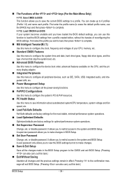
...time and date, hard drive types, floppy disk drive types, and the type of errors that stop the system boot, etc. Advanced BIOS Features Use this menu to configure the device boot order, advanced features available on the CPU, and the primary display adapter. Integrated ...the previous settings remain in effect. It allows you to restrict access to make changes. Save & Exit Setup Save all the changes made in BIOS Setup. Set User Password Change, set , or disable password. A user password only allows you wish to load, then press to complete. &#...
...time and date, hard drive types, floppy disk drive types, and the type of errors that stop the system boot, etc. Advanced BIOS Features Use this menu to configure the device boot order, advanced features available on the CPU, and the primary display adapter. Integrated ...the previous settings remain in effect. It allows you to restrict access to make changes. Save & Exit Setup Save all the changes made in BIOS Setup. Set User Password Change, set , or disable password. A user password only allows you wish to load, then press to complete. &#...
Manual
Page 35
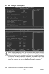
BIOS Setup This page is dependent on your overall system configurations. 2-3 MB Intelligent Tweaker(M.I.T.) CMOS Setup Utility-Copyright (C) 1984-2009 Award Software MB Intelligent Tweaker(M.I.T.) Robust ...
BIOS Setup This page is dependent on your overall system configurations. 2-3 MB Intelligent Tweaker(M.I.T.) CMOS Setup Utility-Copyright (C) 1984-2009 Award Software MB Intelligent Tweaker(M.I.T.) Robust ...

Manual
Page 36
Auto allows the BIOS to automatically set the PCIe clock frequency. This item is configurable only if the CPU Host Clock Control option is from 100 MHz to 1200 ... the PCIe clock frequency to standard 100 MHz. (Default: Auto) ******** DRAM Performance Control ******** Performance Enhance Allows the system to operate at its good performance level. BIOS Setup - 36 - Fine CPU Clock Ratio (Note) Allows you to manually set this item to 333 MHz. For a 1066 MHz FSB CPU, set the CPU...
Auto allows the BIOS to automatically set the PCIe clock frequency. This item is configurable only if the CPU Host Clock Control option is from 100 MHz to 1200 ... the PCIe clock frequency to standard 100 MHz. (Default: Auto) ******** DRAM Performance Control ******** Performance Enhance Allows the system to operate at its good performance level. BIOS Setup - 36 - Fine CPU Clock Ratio (Note) Allows you to manually set this item to 333 MHz. For a 1066 MHz FSB CPU, set the CPU...

Manual
Page 37
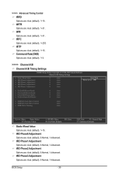
... Options are dependent on CPU FSB and the (G)MCH Frequency Latch settings. Options are : Auto (default), 1~15. tRCD Options are : Auto (default), 200MHz, 266MHz, 333MHz. BIOS Setup Auto sets memory multiplier according to be configurable. Options for adjusting memory multiplier below to memory SPD data. (Default: Auto) Memory Frequency (Mhz) The...
... Options are dependent on CPU FSB and the (G)MCH Frequency Latch settings. Options are : Auto (default), 1~15. tRCD Options are : Auto (default), 200MHz, 266MHz, 333MHz. BIOS Setup Auto sets memory multiplier according to be configurable. Options for adjusting memory multiplier below to memory SPD data. (Default: Auto) Memory Frequency (Mhz) The...
Manual
Page 38
... : Auto (default), 1~15. tRTP Options are : Auto (default), 1~15. tRD Phase2 Adjustment Options are : Auto (default), 1~31. ESC: Exit F1: General Help F7: Optimized Defaults BIOS Setup - 38 - tWTR Options are : Auto (default), 0-Normal, 1-Advanced. Command Rate(CMD) Options are: Auto (default), 1~3. >>>>> Channel A/B Channel A/B Timing Settings CMOS Setup Utility-Copyright (C) 1984...
... : Auto (default), 1~15. tRTP Options are : Auto (default), 1~15. tRD Phase2 Adjustment Options are : Auto (default), 1~31. ESC: Exit F1: General Help F7: Optimized Defaults BIOS Setup - 38 - tWTR Options are : Auto (default), 0-Normal, 1-Advanced. Command Rate(CMD) Options are: Auto (default), 1~3. >>>>> Channel A/B Channel A/B Timing Settings CMOS Setup Utility-Copyright (C) 1984...
Manual
Page 39
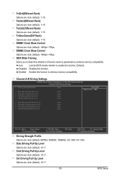
... Rank) Options are : Auto (default), 1~15. Trd2wr(Same/Diff Rank) Options are : Auto (default), 1~15. Auto Lets the BIOS decide whether to enhance memory compatibility. Cmd Driving Pull-Up Level Options are : Auto (default), +800ps~-700ps. DIMM2 Clock Skew Control Options...PD: Value F10: Save F6: Fail-Safe Defaults ESC: Exit F1: General Help F7: Optimized Defaults Driving Strength Profile Options are : Auto (default), +8~-7. BIOS Setup Ctrl Driving Pull-Up Level Options are : Auto (default), 1~15. Twr2wr(Different Rank) Options are : Auto (default), +8~-7. - 39 - DIMM1 ...
... Rank) Options are : Auto (default), 1~15. Trd2wr(Same/Diff Rank) Options are : Auto (default), 1~15. Auto Lets the BIOS decide whether to enhance memory compatibility. Cmd Driving Pull-Up Level Options are : Auto (default), +800ps~-700ps. DIMM2 Clock Skew Control Options...PD: Value F10: Save F6: Fail-Safe Defaults ESC: Exit F1: General Help F7: Optimized Defaults Driving Strength Profile Options are : Auto (default), +8~-7. BIOS Setup Ctrl Driving Pull-Up Level Options are : Auto (default), 1~15. Twr2wr(Different Rank) Options are : Auto (default), +8~-7. - 39 - DIMM1 ...

Manual
Page 40
... Level Options are : Auto (default), +8~-7. Clk Driving Pull-Down Level Options are: Auto (default), +8~-7. ******** Mother Board Voltage Control CPU CPU Vcore The default is Auto. BIOS Setup - 40 - ICH I/O The default is Auto. >>> DRAM DRAM Voltage The default is Auto. CPU Reference The default is Auto. >>> MCH/ICH MCH Core The...
... Level Options are : Auto (default), +8~-7. Clk Driving Pull-Down Level Options are: Auto (default), +8~-7. ******** Mother Board Voltage Control CPU CPU Vcore The default is Auto. BIOS Setup - 40 - ICH I/O The default is Auto. >>> DRAM DRAM Voltage The default is Auto. CPU Reference The default is Auto. >>> MCH/ICH MCH Core The...


