Manual
Page 7
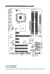
GA-EP35-DS3R/DS3 Motherboard Layout KB_MS RCA_SPDIF R_USB1 R_USB2 R_USB3 ATX_12V LGA775 PHASE LED CPU_FAN ATX GA-EP35-DS3R/DS3 DDRII1 USB_LAN F_AUDIO AUDIO SYS_FAN1 PCIE_3 PCIE_16 RTL8111B PCIE_1 SPDIF_O PCIE_2 CODEC PCI1 SPDIF_I PCI2 IT8718 CD_IN PCI3 COMA Intel® P35 FDD DDRII3 DDRII4 DDRII2 PWR_FAN BATTERY Intel® ICH9R Intel® ICH9 SATAII2 CLR_CMOS SATAII3 GSATAII0 GIGABYTE SATA2 GSATAII1 SATAII0 SATAII1 SATAII4 SATAII5 IDE1 F_USB2 F_USB1 M_BIOS CI F_PANEL LPT B_BIOS PWR_LED SYS_FAN2 Only for GA-EP35-DS3. - 7 - Only for GA-EP35-DS3R.
GA-EP35-DS3R/DS3 Motherboard Layout KB_MS RCA_SPDIF R_USB1 R_USB2 R_USB3 ATX_12V LGA775 PHASE LED CPU_FAN ATX GA-EP35-DS3R/DS3 DDRII1 USB_LAN F_AUDIO AUDIO SYS_FAN1 PCIE_3 PCIE_16 RTL8111B PCIE_1 SPDIF_O PCIE_2 CODEC PCI1 SPDIF_I PCI2 IT8718 CD_IN PCI3 COMA Intel® P35 FDD DDRII3 DDRII4 DDRII2 PWR_FAN BATTERY Intel® ICH9R Intel® ICH9 SATAII2 CLR_CMOS SATAII3 GSATAII0 GIGABYTE SATA2 GSATAII1 SATAII0 SATAII1 SATAII4 SATAII5 IDE1 F_USB2 F_USB1 M_BIOS CI F_PANEL LPT B_BIOS PWR_LED SYS_FAN2 Only for GA-EP35-DS3. - 7 - Only for GA-EP35-DS3R.
Manual
Page 22
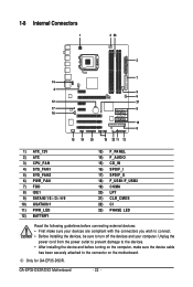
Only for GA-EP35-DS3R. 1-8 Internal Connectors 1 3 23 2 7 14 4 5 6 12 21 17 9 16 10 8 15 19 20 18 22 11 13 1) ATX_12V 2) ATX 3) CPU_FAN 4) SYS_FAN1 5) SYS_FAN2 6) PWR_FAN 7) FDD 8) IDE1 9) SATAII0/1/2 /3 /4/5 ... 20) LPT 21) CLR_CMOS 22) CI 23) PHASE LED Read the following guidelines before turning on the computer, make sure your devices are compliant with the connectors you wish to connect. • Before installing the devices, be sure to the connector on the motherboard. GA-EP35-DS3R/DS3 Motherboard - 22 - Unplug the power cord from...
Only for GA-EP35-DS3R. 1-8 Internal Connectors 1 3 23 2 7 14 4 5 6 12 21 17 9 16 10 8 15 19 20 18 22 11 13 1) ATX_12V 2) ATX 3) CPU_FAN 4) SYS_FAN1 5) SYS_FAN2 6) PWR_FAN 7) FDD 8) IDE1 9) SATAII0/1/2 /3 /4/5 ... 20) LPT 21) CLR_CMOS 22) CI 23) PHASE LED Read the following guidelines before turning on the computer, make sure your devices are compliant with the connectors you wish to connect. • Before installing the devices, be sure to the connector on the motherboard. GA-EP35-DS3R/DS3 Motherboard - 22 - Unplug the power cord from...
Manual
Page 33
Definition 1 Signal 1 2 GND 23) PHASE LED The number of lighted LEDs. - 33 - The higher the CPU loading, the more the number of lighted LEDs indicates the CPU loading. This function requires a chassis with chassis intrusion detection design. Hardware Installation 22) CI (Chassis Intrusion Header) This motherboard provides a chassis detection feature that detects if the chassis cover has been removed. Pin No.
Definition 1 Signal 1 2 GND 23) PHASE LED The number of lighted LEDs. - 33 - The higher the CPU loading, the more the number of lighted LEDs indicates the CPU loading. This function requires a chassis with chassis intrusion detection design. Hardware Installation 22) CI (Chassis Intrusion Header) This motherboard provides a chassis detection feature that detects if the chassis cover has been removed. Pin No.
Manual
Page 74
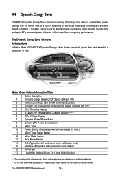
... Energy Saver is able to provide exceptional power savings of a button. Meter Mode In Meter Mode, GIGABYTE's Dynamic Energy Saver shows how much power they have saved in taskbar.) 16 INFO/Help 17 Live Utility Update (Check For...motherboard model. • CPU Power and Power Scores are for reference only. GA-EP35-DS3R/DS3 Motherboard - 74 - The Dynamic Energy Saver Interface A. Button Information Table Button Description 1 Dynamic Energy Saver On/Off Switch (Default: Off) 2 Motherboard Phase LED On/Off Switch (Default: On) 3 Dynamic CPU Frequency Function On/Off ...
... Energy Saver is able to provide exceptional power savings of a button. Meter Mode In Meter Mode, GIGABYTE's Dynamic Energy Saver shows how much power they have saved in taskbar.) 16 INFO/Help 17 Live Utility Update (Check For...motherboard model. • CPU Power and Power Scores are for reference only. GA-EP35-DS3R/DS3 Motherboard - 74 - The Dynamic Energy Saver Interface A. Button Information Table Button Description 1 Dynamic Energy Saver On/Off Switch (Default: Off) 2 Motherboard Phase LED On/Off Switch (Default: On) 3 Dynamic CPU Frequency Function On/Off ...
Manual
Page 75
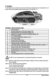
... Button Description 1 Dynamic Energy Saver On/Off Switch (Default: Off) 2 Motherboard Phase LED On/Off Switch (Default: On) 3 Dynamic CPU Frequency Function On/Off Switch (Default: Off) 4 CPU Throttling Display 5 3-Level CPU Voltage Switch (Default: Level 1) 6 CPU Voltage Display 7 Dynamic Power Phase Status 8 Current CPU Power Consumption 9 Time/Date Dynamic Energy Saver Enabled...
... Button Description 1 Dynamic Energy Saver On/Off Switch (Default: Off) 2 Motherboard Phase LED On/Off Switch (Default: On) 3 Dynamic CPU Frequency Function On/Off Switch (Default: Off) 4 CPU Throttling Display 5 3-Level CPU Voltage Switch (Default: Level 1) 6 CPU Voltage Display 7 Dynamic Power Phase Status 8 Current CPU Power Consumption 9 Time/Date Dynamic Energy Saver Enabled...


