
Manual
Page 4
Table of Contents Box Contents ...6 OptionalItems ...6 GA-EP35-DS3R/DS3 Motherboard Layout 7 Block Diagram ...8 Chapter 1 Hardware Installation 9 1-1 Installation Precautions 9 1-2 Product Specifications 10 1-3 Installing the CPU and CPU Cooler 13 1-3-1 Installing the CPU 13 1-3-2 Installing the CPU ...
Table of Contents Box Contents ...6 OptionalItems ...6 GA-EP35-DS3R/DS3 Motherboard Layout 7 Block Diagram ...8 Chapter 1 Hardware Installation 9 1-1 Installation Precautions 9 1-2 Product Specifications 10 1-3 Installing the CPU and CPU Cooler 13 1-3-1 Installing the CPU 13 1-3-2 Installing the CPU ...
Manual
Page 6
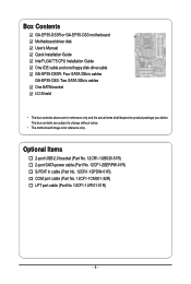
... No. 12CF1-1LP001-01R) - 6 - Box Contents GA-EP35-DS3R or GA-EP35-DS3 motherboard Motherboard driver disk User's Manual Quick Installation Guide Intel® LGA775 CPU Installation Guide One IDE cable and one floppy disk drive cable GA-EP35-DS3R: Four SATA 3Gb/s cables GA-EP35-DS3: Two SATA 3Gb/s cables One SATA bracket I/O Shield... • The box contents above are subject to change without notice. • The motherboard image is for reference only and the...
... No. 12CF1-1LP001-01R) - 6 - Box Contents GA-EP35-DS3R or GA-EP35-DS3 motherboard Motherboard driver disk User's Manual Quick Installation Guide Intel® LGA775 CPU Installation Guide One IDE cable and one floppy disk drive cable GA-EP35-DS3R: Four SATA 3Gb/s cables GA-EP35-DS3: Two SATA 3Gb/s cables One SATA bracket I/O Shield... • The box contents above are subject to change without notice. • The motherboard image is for reference only and the...
Manual
Page 7
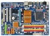
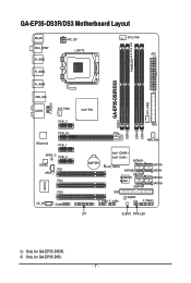
Only for GA-EP35-DS3R. GA-EP35-DS3R/DS3 Motherboard Layout KB_MS RCA_SPDIF R_USB1 R_USB2 R_USB3 ATX_12V LGA775 PHASE LED CPU_FAN ATX GA-EP35-DS3R/DS3 DDRII1 USB_LAN F_AUDIO AUDIO SYS_FAN1 PCIE_3 PCIE_16 RTL8111B PCIE_1 SPDIF_O PCIE_2 CODEC PCI1 SPDIF_I PCI2 IT8718 CD_IN PCI3 COMA Intel® P35 FDD DDRII3 DDRII4 DDRII2 PWR_FAN BATTERY Intel® ICH9R Intel® ICH9 SATAII2 CLR_CMOS SATAII3 GSATAII0 GIGABYTE SATA2 GSATAII1 SATAII0 SATAII1 SATAII4 SATAII5 IDE1 F_USB2 F_USB1 M_BIOS CI F_PANEL LPT B_BIOS PWR_LED SYS_FAN2 Only for GA-EP35-DS3. - 7 -
Only for GA-EP35-DS3R. GA-EP35-DS3R/DS3 Motherboard Layout KB_MS RCA_SPDIF R_USB1 R_USB2 R_USB3 ATX_12V LGA775 PHASE LED CPU_FAN ATX GA-EP35-DS3R/DS3 DDRII1 USB_LAN F_AUDIO AUDIO SYS_FAN1 PCIE_3 PCIE_16 RTL8111B PCIE_1 SPDIF_O PCIE_2 CODEC PCI1 SPDIF_I PCI2 IT8718 CD_IN PCI3 COMA Intel® P35 FDD DDRII3 DDRII4 DDRII2 PWR_FAN BATTERY Intel® ICH9R Intel® ICH9 SATAII2 CLR_CMOS SATAII3 GSATAII0 GIGABYTE SATA2 GSATAII1 SATAII0 SATAII1 SATAII4 SATAII5 IDE1 F_USB2 F_USB1 M_BIOS CI F_PANEL LPT B_BIOS PWR_LED SYS_FAN2 Only for GA-EP35-DS3. - 7 -
Manual
Page 10
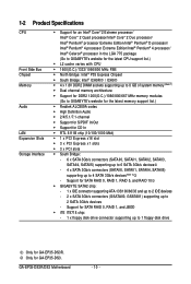
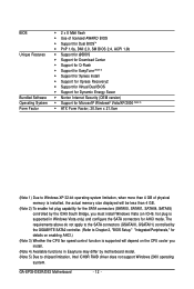
...; D processor/ Intel® Pentium® 4 processor Extreme Edition/Intel® Pentium® 4 processor/ Intel® Celeron® processor in the LGA 775 package (Go to GIGABYTE's website for the latest CPU support list.) Š L2 cache varies with CPU Š 1600(O.C.)/1333/1066/800 MHz FSB Š North Bridge: Intel®..., SATAII1, SATAII2, SATAII3, SATAII4, SATAII5) supporting up to 6 SATA 3Gb/s devices - 4 x SATA 3Gb/s connectors (SATAII0, SATAII1, SATAII4, SATAII5) supporting up to 4 SATA 3Gb/s devices(Note 2) - GA-EP35-DS3R/DS3 Motherboard - 10 -
...; D processor/ Intel® Pentium® 4 processor Extreme Edition/Intel® Pentium® 4 processor/ Intel® Celeron® processor in the LGA 775 package (Go to GIGABYTE's website for the latest CPU support list.) Š L2 cache varies with CPU Š 1600(O.C.)/1333/1066/800 MHz FSB Š North Bridge: Intel®..., SATAII1, SATAII2, SATAII3, SATAII4, SATAII5) supporting up to 6 SATA 3Gb/s devices - 4 x SATA 3Gb/s connectors (SATAII0, SATAII1, SATAII4, SATAII5) supporting up to 4 SATA 3Gb/s devices(Note 2) - GA-EP35-DS3R/DS3 Motherboard - 10 -
Manual
Page 12
GA-EP35-DS3R/DS3 Motherboard - 12 - The requirements above do not apply to the SATA connectors (GSATAII0, GSATAII1) controlled by the GIGABYTE SATA2 controller. (Refer to Chapter 2, "BIOS Setup," "Integrated Peripherals," for details on enabling AHCI.) (Note 3) Whether the CPU fan... speed control function is supported will depend on ICH9, hot plug is supported in Easytune may differ by motherboard model. (Note 5) Due ...
GA-EP35-DS3R/DS3 Motherboard - 12 - The requirements above do not apply to the SATA connectors (GSATAII0, GSATAII1) controlled by the GIGABYTE SATA2 controller. (Refer to Chapter 2, "BIOS Setup," "Integrated Peripherals," for details on enabling AHCI.) (Note 3) Whether the CPU fan... speed control function is supported will depend on ICH9, hot plug is supported in Easytune may differ by motherboard model. (Note 5) Due ...

Manual
Page 14
... steps below to the CPU. Step 5: Once the CPU is properly inserted, replace the load plate and push the CPU socket lever back into the motherboard CPU socket. B. Step 4: Hold the CPU with the socket alignment keys) and gently insert the CPU into position. GA-EP35-DS3R/DS3 Motherboard - 14 -
... steps below to the CPU. Step 5: Once the CPU is properly inserted, replace the load plate and push the CPU socket lever back into the motherboard CPU socket. B. Step 4: Hold the CPU with the socket alignment keys) and gently insert the CPU into position. GA-EP35-DS3R/DS3 Motherboard - 14 -
Manual
Page 16
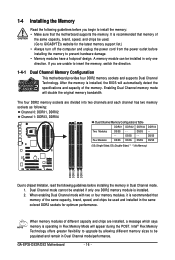
...different capacity and chips are installed, a message which says memory is installed. 2. Four Modules DS/SS DS/SS DS/SS DDRII4 - GA-EP35-DS3R/DS3 Motherboard - 16 - When memory modules of the same capacity, brand, speed, and chips be used and installed in the same colored DDR2 ...Dual Channel memory mode will automatically detect the specifications and capacity of the same capacity, brand, speed, and chips be used . (Go to GIGABYTE's website for optimum performance. DS/SS - - DS/SS DS/SS (SS=Single-Sided, DS=Double-Sided, "- -"=No Memory) DDRII1 DDRII2...
...different capacity and chips are installed, a message which says memory is installed. 2. Four Modules DS/SS DS/SS DS/SS DDRII4 - GA-EP35-DS3R/DS3 Motherboard - 16 - When memory modules of the same capacity, brand, speed, and chips be used and installed in the same colored DDR2 ...Dual Channel memory mode will automatically detect the specifications and capacity of the same capacity, brand, speed, and chips be used . (Go to GIGABYTE's website for optimum performance. DS/SS - - DS/SS DS/SS (SS=Single-Sided, DS=Double-Sided, "- -"=No Memory) DDRII1 DDRII2...
Manual
Page 18
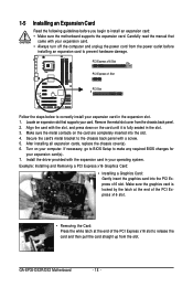
... fully seated in the slot. 3. 1-5 Installing an Expansion Card Read the following guidelines before installing an expansion card to prevent hardware damage. GA-EP35-DS3R/DS3 Motherboard - 18 - Remove the metal slot cover from the slot. Align the card with your expansion card. • Always turn off the ... Express x16 Slot PCI Express x1 Slot PCI Slot Follow the steps below to install an expansion card: • Make sure the motherboard supports the expansion card. Secure the card's metal bracket to make any required BIOS changes for your operating system. Install the driver ...
... fully seated in the slot. 3. 1-5 Installing an Expansion Card Read the following guidelines before installing an expansion card to prevent hardware damage. GA-EP35-DS3R/DS3 Motherboard - 18 - Remove the metal slot cover from the slot. Align the card with your expansion card. • Always turn off the ... Express x16 Slot PCI Express x1 Slot PCI Slot Follow the steps below to install an expansion card: • Make sure the motherboard supports the expansion card. Secure the card's metal bracket to make any required BIOS changes for your operating system. Install the driver ...
Manual
Page 20
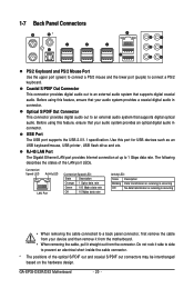
...data transmission or receiving is occurring • When removing the cable connected to an external audio system that supports digital coaxial audio. GA-EP35-DS3R/DS3 Motherboard - 20 - Before using this feature, ensure that your audio system provides an optical digital audio in connector. Optical S/PDIF ... first remove the cable from your audio system provides a coaxial digital audio in connector. Do not rock it straight out from the motherboard. • When removing the cable, pull it side to side to an external audio system that supports digital optical audio. Use...
...data transmission or receiving is occurring • When removing the cable connected to an external audio system that supports digital coaxial audio. GA-EP35-DS3R/DS3 Motherboard - 20 - Before using this feature, ensure that your audio system provides an optical digital audio in connector. Optical S/PDIF ... first remove the cable from your audio system provides a coaxial digital audio in connector. Do not rock it straight out from the motherboard. • When removing the cable, pull it side to side to an external audio system that supports digital optical audio. Use...
Manual
Page 22
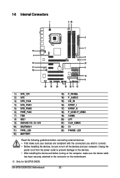
GA-EP35-DS3R/DS3 Motherboard - 22 - Only for GA-EP35-DS3R. Unplug the power cord from the power outlet to prevent damage to the devices. • After installing the device and before connecting external devices: • ..., make sure your devices are compliant with the connectors you wish to connect. • Before installing the devices, be sure to the connector on the motherboard.
GA-EP35-DS3R/DS3 Motherboard - 22 - Only for GA-EP35-DS3R. Unplug the power cord from the power outlet to prevent damage to the devices. • After installing the device and before connecting external devices: • ..., make sure your devices are compliant with the connectors you wish to connect. • Before installing the devices, be sure to the connector on the motherboard.
Manual
Page 24
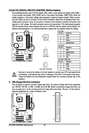
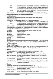
...720 KB, 1.2 MB, 1.44 MB, and 2.88 MB. Overheating may result in the correct orientation. 3/4/5/6) CPU_FAN/SYS_FAN1/SYS_FAN2/PWR_FAN (Fan Headers) The motherboard has a 4-pin CPU fan header (CPU_FAN), a 3-pin system fan header (SYS_FAN1), a 4-pin system fan header (SYS_FAN2) and a 3-pin power ...the connector and the floppy disk drive cable. Before connecting a floppy disk drive, be sure to locate pin 1 of different color. 34 33 GA-EP35-DS3R/DS3 Motherboard 2 1 - 24 - When connecting a fan cable, be sure to connect it is the ground wire. Each fan header supplies a +...
...720 KB, 1.2 MB, 1.44 MB, and 2.88 MB. Overheating may result in the correct orientation. 3/4/5/6) CPU_FAN/SYS_FAN1/SYS_FAN2/PWR_FAN (Fan Headers) The motherboard has a 4-pin CPU fan header (CPU_FAN), a 3-pin system fan header (SYS_FAN1), a 4-pin system fan header (SYS_FAN2) and a 3-pin power ...the connector and the floppy disk drive cable. Before connecting a floppy disk drive, be sure to locate pin 1 of different color. 34 33 GA-EP35-DS3R/DS3 Motherboard 2 1 - 24 - When connecting a fan cable, be sure to connect it is the ground wire. Each fan header supplies a +...
Manual
Page 26
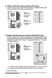
...connect the L-shaped end of hard drives must be used, the total number of the SATA 3Gb/s cable to Chapter 5, "Configuring SATA Hard Drive(s)," for GA-EP35-DS3. Each SATA connector supports a single SATA device. 7 1 SATAII0 SATAII1 1 7 7 1 SATAII4 SATAII5 1 7 Pin No. 1 2 3 4 ... standard. A RAID 0 or RAID 1 configuration requires at least two hard drives. GA-EP35-DS3R/DS3 Motherboard - 26 - If more than two hard drives are compatible with SATA 1.5Gb/s standard. The GIGABYTE SATA2 controller supports RAID 0 and RAID 1. Pin No. Only for instructions on configuring ...
...connect the L-shaped end of hard drives must be used, the total number of the SATA 3Gb/s cable to Chapter 5, "Configuring SATA Hard Drive(s)," for GA-EP35-DS3. Each SATA connector supports a single SATA device. 7 1 SATAII0 SATAII1 1 7 7 1 SATAII4 SATAII5 1 7 Pin No. 1 2 3 4 ... standard. A RAID 0 or RAID 1 configuration requires at least two hard drives. GA-EP35-DS3R/DS3 Motherboard - 26 - If more than two hard drives are compatible with SATA 1.5Gb/s standard. The GIGABYTE SATA2 controller supports RAID 0 and RAID 1. Pin No. Only for instructions on configuring ...

Manual
Page 28
... startup status by chassis. Message/Power/ Power Sleep LED Switch Speaker MSG+ MSG- One single short beep will be heard if no problem is operating. GA-EP35-DS3R/DS3 Motherboard - 28 - When connecting your system using the power switch (refer to Chapter 2, "BIOS Setup," "Power Management Setup," for information about beep codes. • HD (Hard...
... startup status by chassis. Message/Power/ Power Sleep LED Switch Speaker MSG+ MSG- One single short beep will be heard if no problem is operating. GA-EP35-DS3R/DS3 Motherboard - 28 - When connecting your system using the power switch (refer to Chapter 2, "BIOS Setup," "Power Management Setup," for information about beep codes. • HD (Hard...
Manual
Page 30
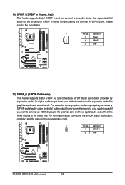
... example, some graphics cards may require you to use a S/PDIF digital audio cable for digital audio output from your motherboard to your graphics card if you wish to connect an HDMI display to certain expansion cards like graphics cards and sound ...digital S/PDIF out and connects a S/PDIF digital audio cable (provided by expansion cards) for your motherboard to the graphics card and have digital audio output from your expansion card. 1 Pin No. Definition 1 SPDIFO 2 GND GA-EP35-DS3R/DS3 Motherboard - 30 - 16) SPDIF_I (S/PDIF In Header, Red) This header supports digital S/PDIF in...
... example, some graphics cards may require you to use a S/PDIF digital audio cable for digital audio output from your motherboard to your graphics card if you wish to connect an HDMI display to certain expansion cards like graphics cards and sound ...digital S/PDIF out and connects a S/PDIF digital audio cable (provided by expansion cards) for your motherboard to the graphics card and have digital audio output from your expansion card. 1 Pin No. Definition 1 SPDIFO 2 GND GA-EP35-DS3R/DS3 Motherboard - 30 - 16) SPDIF_I (S/PDIF In Header, Red) This header supports digital S/PDIF in...

Manual
Page 32
... on the two pins to temporarily short the two pins or use a metal object like a screwdriver to remove the jumper cap from the jumper. GA-EP35-DS3R/DS3 Motherboard - 32 - Open: Normal Short: Clear CMOS Values • Always turn off your computer, be sure to touch the two pins for BIOS ...BIOS configurations) and reset the CMOS values to Chapter 2, "BIOS Setup," for a few seconds. Failure to do so may cause damage to the motherboard. • After system restart, go to BIOS Setup to load factory defaults (select Load Optimized Defaults) or manually configure the BIOS settings (refer...
... on the two pins to temporarily short the two pins or use a metal object like a screwdriver to remove the jumper cap from the jumper. GA-EP35-DS3R/DS3 Motherboard - 32 - Open: Normal Short: Clear CMOS Values • Always turn off your computer, be sure to touch the two pins for BIOS ...BIOS configurations) and reset the CMOS values to Chapter 2, "BIOS Setup," for a few seconds. Failure to do so may cause damage to the motherboard. • After system restart, go to BIOS Setup to load factory defaults (select Load Optimized Defaults) or manually configure the BIOS settings (refer...

Manual
Page 34
GA-EP35-DS3R/DS3 Motherboard - 34 -
GA-EP35-DS3R/DS3 Motherboard - 34 -

Manual
Page 36
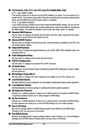
... Copyright (C) 1984-2007, Award Software, Inc. A. Note: The setting in Boot Menu. The system will still be used for one time only. GA-EP35-DS3R/DS3 Motherboard - 36 - To exit Boot Menu, press . For more information, refer to Chapter 4, "Xpress Recovery2." : Boot Menu Boot Menu allows you...Press the key to enter BIOS Setup. : Xpress Recovery2 If you to accept. 2-1 Startup Screen The following screens may appear when the computer boots. EP35-DS3R F1b . . . . : BIOS Setup : XpressRecovery2 : Boot Menu : Qflash 12/04/2007-P35-ICH9-6A89OG0NC-00 Function Keys Function Keys: :...
... Copyright (C) 1984-2007, Award Software, Inc. A. Note: The setting in Boot Menu. The system will still be used for one time only. GA-EP35-DS3R/DS3 Motherboard - 36 - To exit Boot Menu, press . For more information, refer to Chapter 4, "Xpress Recovery2." : Boot Menu Boot Menu allows you...Press the key to enter BIOS Setup. : Xpress Recovery2 If you to accept. 2-1 Startup Screen The following screens may appear when the computer boots. EP35-DS3R F1b . . . . : BIOS Setup : XpressRecovery2 : Boot Menu : Qflash 12/04/2007-P35-ICH9-6A89OG0NC-00 Function Keys Function Keys: :...
Manual
Page 38
... previous settings remain in the BIOS Setup program to the system and BIOS Setup. First select the profile you can also carry out this task.) GA-EP35-DS3R/DS3 Motherboard - 38 - A supervisor password allows you to configure the clock, frequency and voltages of your system becomes unstable and you have loaded the BIOS default settings...
... previous settings remain in the BIOS Setup program to the system and BIOS Setup. First select the profile you can also carry out this task.) GA-EP35-DS3R/DS3 Motherboard - 38 - A supervisor password allows you to configure the clock, frequency and voltages of your system becomes unstable and you have loaded the BIOS default settings...
Manual
Page 40
... will not stop for a keyboard or a floppy disk drive error but it will not stop for faster system startup. Extended Memory The amount of heads. GA-EP35-DS3R/DS3 Motherboard - 40 - • Auto • None • Manual Access Mode Lets BIOS automatically detect IDE/SATA devices during the POST. (Default) If no IDE/SATA devices...
... will not stop for a keyboard or a floppy disk drive error but it will not stop for faster system startup. Extended Memory The amount of heads. GA-EP35-DS3R/DS3 Motherboard - 40 - • Auto • None • Manual Access Mode Lets BIOS automatically detect IDE/SATA devices during the POST. (Default) If no IDE/SATA devices...

Manual
Page 42
... installed PCI graphics card or the PCI Express graphics card. For more information about Intel CPUs' unique features, please visit Intel's website. GA-EP35-DS3R/DS3 Motherboard - 42 - When enabled, the CPU core frequency and voltage will be reduced when the CPU is present only if you to determine... Disable Bit function. With virtualization, one computer system can dynamically and effectively lower the CPU voltage and core frequency to display the GIGABYTE Logo at system startup. PCI Sets the PCI graphics card as the first display. (Default) PEG Sets the PCI Express graphics card...
... installed PCI graphics card or the PCI Express graphics card. For more information about Intel CPUs' unique features, please visit Intel's website. GA-EP35-DS3R/DS3 Motherboard - 42 - When enabled, the CPU core frequency and voltage will be reduced when the CPU is present only if you to determine... Disable Bit function. With virtualization, one computer system can dynamically and effectively lower the CPU voltage and core frequency to display the GIGABYTE Logo at system startup. PCI Sets the PCI graphics card as the first display. (Default) PEG Sets the PCI Express graphics card...


