
Manual
Page 25
... LED Connects to the reset switch on the chassis front panel. The system reports system startup status by chassis. Hardware Installation Message/Power/ Power Sleep LED Switch Speaker MSG+ MSG- When connecting your system using the power switch (refer to Chapter 2, "BIOS Setup," "Power Management Setup...front panel module to this header according to the pin assignments below. 10) F_PANEL (Front Panel Header) Connect the power switch, reset switch, speaker and system status indicator on the chassis front panel to this header, make sure the wire assignments and the pin...
... LED Connects to the reset switch on the chassis front panel. The system reports system startup status by chassis. Hardware Installation Message/Power/ Power Sleep LED Switch Speaker MSG+ MSG- When connecting your system using the power switch (refer to Chapter 2, "BIOS Setup," "Power Management Setup...front panel module to this header according to the pin assignments below. 10) F_PANEL (Front Panel Header) Connect the power switch, reset switch, speaker and system status indicator on the chassis front panel to this header, make sure the wire assignments and the pin...

Manual
Page 29
... jumper cap from the jumper. Definition 1 1 Signal 2 GND 18) CLR_CMOS (Clearing CMOS Jumper) Use this jumper to factory defaults. Pin No. date information and BIOS configurations) and reset the CMOS values to clear the CMOS values (e.g. Failure to do so may cause damage to the motherboard. • After system restart, go to...
... jumper cap from the jumper. Definition 1 1 Signal 2 GND 18) CLR_CMOS (Clearing CMOS Jumper) Use this jumper to factory defaults. Pin No. date information and BIOS configurations) and reset the CMOS values to clear the CMOS values (e.g. Failure to do so may cause damage to the motherboard. • After system restart, go to...

Manual
Page 31
... program, press the key during the POST when the power is potentially risky, if you not flash the BIOS. If this occurs, try to clear the CMOS values and reset the board to default values. (Refer to the "Load Optimized Defaults" section in this chapter or introductions... to) to prevent system instability or other unexpected results. Chapter 2 BIOS Setup BIOS (Basic Input and Output System) records hardware parameters of the system in system's failure to boot. To upgrade the BIOS, use either the GIGABYTE Q-Flash or @BIOS utility. • Q-Flash allows the user to quickly and easily ...
... program, press the key during the POST when the power is potentially risky, if you not flash the BIOS. If this occurs, try to clear the CMOS values and reset the board to default values. (Refer to the "Load Optimized Defaults" section in this chapter or introductions... to) to prevent system instability or other unexpected results. Chapter 2 BIOS Setup BIOS (Basic Input and Output System) records hardware parameters of the system in system's failure to boot. To upgrade the BIOS, use either the GIGABYTE Q-Flash or @BIOS utility. • Q-Flash allows the user to quickly and easily ...
Manual
Page 45
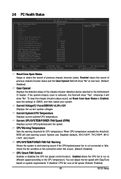
...Sets the warning threshold for CPU temperature. 2-8 PC Health Status CMOS Setup Utility-Copyright (C) 1984-2007 Award Software PC Health Status Reset Case Open Status Case Opened Vcore DDR18V +3.3V +12V Current System Temperature Current CPU Temperature Current CPU FAN Speed Current SYSTEM FAN1...Case Opened Displays the detection status of the chassis intrusion detection device attached to run at full speed. (Default: Enabled) - 45 - BIOS Setup Enabled clears the record of previous chassis intrusion status. Current CPU/SYSTEM/POWER FAN Speed (RPM) Displays current CPU/system/power fan ...
...Sets the warning threshold for CPU temperature. 2-8 PC Health Status CMOS Setup Utility-Copyright (C) 1984-2007 Award Software PC Health Status Reset Case Open Status Case Opened Vcore DDR18V +3.3V +12V Current System Temperature Current CPU Temperature Current CPU FAN Speed Current SYSTEM FAN1...Case Opened Displays the detection status of the chassis intrusion detection device attached to run at full speed. (Default: Enabled) - 45 - BIOS Setup Enabled clears the record of previous chassis intrusion status. Current CPU/SYSTEM/POWER FAN Speed (RPM) Displays current CPU/system/power fan ...

Manual
Page 47
... overclocking, lower the overclocking ratio. (Note) This item appears only if you install a CPU that the CPU frequency be configurable. BIOS Setup Racing Increases CPU frequency by 7% or 9% depending on CPU loading through the use of 5 preset states. The item is ... C.I.A.2 CPU Intelligent Accelerator 2 (C.I .A.2. (Default) Cruise Increases CPU frequency by 0.5 for automated system reboot, or clear the CMOS values to reset the board to default values. (Default: Disabled) CPU Host Frequency (Mhz) Allows you to enhance the performance of CPU host clock. Robust ...
... overclocking, lower the overclocking ratio. (Note) This item appears only if you install a CPU that the CPU frequency be configurable. BIOS Setup Racing Increases CPU frequency by 7% or 9% depending on CPU loading through the use of 5 preset states. The item is ... C.I.A.2 CPU Intelligent Accelerator 2 (C.I .A.2. (Default) Cruise Increases CPU frequency by 0.5 for automated system reboot, or clear the CMOS values to reset the board to default values. (Default: Disabled) CPU Host Frequency (Mhz) Allows you to enhance the performance of CPU host clock. Robust ...

Manual
Page 63
... return to access Q-Flash. 2. CopUypBdIaOteSBcIoOmSpflerotemd -DPriavses !! The follow procedure assumes that you sure to begin the BIOS update. In the main menu of the system reading the BIOS file from Drive Sa0vfeilBe(IOs)SfotounDdrive KL:Move ESC:Reset :Power Off Total size : 0 Free size : 0 3. B. The monitor will display the update process. • Do...
... return to access Q-Flash. 2. CopUypBdIaOteSBcIoOmSpflerotemd -DPriavses !! The follow procedure assumes that you sure to begin the BIOS update. In the main menu of the system reading the BIOS file from Drive Sa0vfeilBe(IOs)SfotounDdrive KL:Move ESC:Reset :Power Off Total size : 0 Free size : 0 3. B. The monitor will display the update process. • Do...


