Manual
Page 7
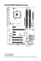
Only for GA-EP35-DS3R. GA-EP35-DS3R/DS3 Motherboard Layout KB_MS RCA_SPDIF R_USB1 R_USB2 R_USB3 ATX_12V LGA775 PHASE LED CPU_FAN ATX GA-EP35-DS3R/DS3 DDRII1 USB_LAN F_AUDIO AUDIO SYS_FAN1 PCIE_3 PCIE_16 RTL8111B PCIE_1 SPDIF_O PCIE_2 CODEC PCI1 SPDIF_I PCI2 IT8718 CD_IN PCI3 COMA Intel® P35 FDD DDRII3 DDRII4 DDRII2 PWR_FAN BATTERY Intel® ICH9R Intel® ICH9 SATAII2 CLR_CMOS SATAII3 GSATAII0 GIGABYTE SATA2 GSATAII1 SATAII0 SATAII1 SATAII4 SATAII5 IDE1 F_USB2 F_USB1 M_BIOS CI F_PANEL LPT B_BIOS PWR_LED SYS_FAN2 Only for GA-EP35-DS3. - 7 -
Only for GA-EP35-DS3R. GA-EP35-DS3R/DS3 Motherboard Layout KB_MS RCA_SPDIF R_USB1 R_USB2 R_USB3 ATX_12V LGA775 PHASE LED CPU_FAN ATX GA-EP35-DS3R/DS3 DDRII1 USB_LAN F_AUDIO AUDIO SYS_FAN1 PCIE_3 PCIE_16 RTL8111B PCIE_1 SPDIF_O PCIE_2 CODEC PCI1 SPDIF_I PCI2 IT8718 CD_IN PCI3 COMA Intel® P35 FDD DDRII3 DDRII4 DDRII2 PWR_FAN BATTERY Intel® ICH9R Intel® ICH9 SATAII2 CLR_CMOS SATAII3 GSATAII0 GIGABYTE SATA2 GSATAII1 SATAII0 SATAII1 SATAII4 SATAII5 IDE1 F_USB2 F_USB1 M_BIOS CI F_PANEL LPT B_BIOS PWR_LED SYS_FAN2 Only for GA-EP35-DS3. - 7 -
Manual
Page 22
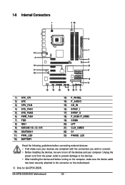
Only for GA-EP35-DS3R. GA-EP35-DS3R/DS3 Motherboard - 22 - Unplug the power cord from the power outlet to prevent damage to the devices. • After installing the device and before connecting external ...) PWR_LED 12) BATTERY 13) F_PANEL 14) F_AUDIO 15) CD_IN 16) SPDIF_I 17) SPDIF_O 18) F_USB1/F_USB2 19) COMA 20) LPT 21) CLR_CMOS 22) CI 23) PHASE LED Read the following guidelines before turning on the computer, make sure your devices are compliant with the connectors you wish to connect. • Before installing...
Only for GA-EP35-DS3R. GA-EP35-DS3R/DS3 Motherboard - 22 - Unplug the power cord from the power outlet to prevent damage to the devices. • After installing the device and before connecting external ...) PWR_LED 12) BATTERY 13) F_PANEL 14) F_AUDIO 15) CD_IN 16) SPDIF_I 17) SPDIF_O 18) F_USB1/F_USB2 19) COMA 20) LPT 21) CLR_CMOS 22) CI 23) PHASE LED Read the following guidelines before turning on the computer, make sure your devices are compliant with the connectors you wish to connect. • Before installing...
Manual
Page 33
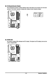
Hardware Installation Definition 1 Signal 1 2 GND 23) PHASE LED The number of lighted LEDs. - 33 - The higher the CPU loading, the more the number of lighted LEDs indicates the CPU loading. Pin No. This function requires a chassis with chassis intrusion detection design. 22) CI (Chassis Intrusion Header) This motherboard provides a chassis detection feature that detects if the chassis cover has been removed.
Hardware Installation Definition 1 Signal 1 2 GND 23) PHASE LED The number of lighted LEDs. - 33 - The higher the CPU loading, the more the number of lighted LEDs indicates the CPU loading. Pin No. This function requires a chassis with chassis intrusion detection design. 22) CI (Chassis Intrusion Header) This motherboard provides a chassis detection feature that detects if the chassis cover has been removed.
Manual
Page 74
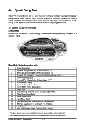
...savings with the simple click of time. Button Information Table Button Description 1 Dynamic Energy Saver On/Off Switch (Default: Off) 2 Motherboard Phase LED On/Off Switch (Default: On) 3 Dynamic CPU Frequency Function On/Off Switch (Default: Off) (Note 1) 4 CPU Throttling Display ...area.) 15 Minimize (Application will continue to 20% improved power efficiency without sacrificing computing performance. GA-EP35-DS3R/DS3 Motherboard - 74 - 4-4 Dynamic Energy Saver GIGABYTE Dynamic Energy Saver is for reference only. Actual results may vary depending on testing method. The ...
...savings with the simple click of time. Button Information Table Button Description 1 Dynamic Energy Saver On/Off Switch (Default: Off) 2 Motherboard Phase LED On/Off Switch (Default: On) 3 Dynamic CPU Frequency Function On/Off Switch (Default: Off) (Note 1) 4 CPU Throttling Display ...area.) 15 Minimize (Application will continue to 20% improved power efficiency without sacrificing computing performance. GA-EP35-DS3R/DS3 Motherboard - 74 - 4-4 Dynamic Energy Saver GIGABYTE Dynamic Energy Saver is for reference only. Actual results may vary depending on testing method. The ...
Manual
Page 75
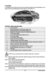
...first time (Note 3). B. Total Mode - Button Information Table Button Description 1 Dynamic Energy Saver On/Off Switch (Default: Off) 2 Motherboard Phase LED On/Off Switch (Default: On) 3 Dynamic CPU Frequency Function On/Off Switch (Default: Off) 4 CPU Throttling Display 5 3-Level CPU ...Voltage Switch (Default: Level 1) 6 CPU Voltage Display 7 Dynamic Power Phase Status 8 Current CPU Power Consumption 9 Time/Date Dynamic Energy Saver Enabled 10 Total Power Savings (Total power saving with Dynamic Energy Saver ...
...first time (Note 3). B. Total Mode - Button Information Table Button Description 1 Dynamic Energy Saver On/Off Switch (Default: Off) 2 Motherboard Phase LED On/Off Switch (Default: On) 3 Dynamic CPU Frequency Function On/Off Switch (Default: Off) 4 CPU Throttling Display 5 3-Level CPU ...Voltage Switch (Default: Level 1) 6 CPU Voltage Display 7 Dynamic Power Phase Status 8 Current CPU Power Consumption 9 Time/Date Dynamic Energy Saver Enabled 10 Total Power Savings (Total power saving with Dynamic Energy Saver ...


