Manual
Page 3
... product, carefully read the User's Manual. „„ For product-related information, check on our website at: http://www.gigabyte.com Identifying Your Motherboard Revision The revision number on your motherboard revision before updating motherboard BIOS, drivers, or when looking for technical information. Copyright © 2012 GIGA-BYTE TECHNOLOGY CO., LTD. All rights reserved. Changes...
... product, carefully read the User's Manual. „„ For product-related information, check on our website at: http://www.gigabyte.com Identifying Your Motherboard Revision The revision number on your motherboard revision before updating motherboard BIOS, drivers, or when looking for technical information. Copyright © 2012 GIGA-BYTE TECHNOLOGY CO., LTD. All rights reserved. Changes...
Manual
Page 4
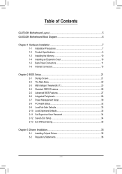
Table of Contents GA-E240N Motherboard Layout 5 GA-E240N Motherboard Block Diagram 6 Chapter 1 Hardware Installation 7 1-1 Installation Precautions 7 1-2 Product Specifications 8 1-3 Installing the Memory 10 1-4 Installing an Expansion Card 10 1-5 Back Panel Connectors 11 1-6 Internal Connectors 13 ...-Safe Defaults 33 2-10 Load Optimized Defaults 33 2-11 Set Supervisor/User Password 34 2-12 Save & Exit Setup 34 2-13 Exit Without Saving 35 Chapter 3 Drivers Installation 35 3-1 Installing Chipset Drivers 35 3-2 Regulatory Statements 36 - 4 -
Table of Contents GA-E240N Motherboard Layout 5 GA-E240N Motherboard Block Diagram 6 Chapter 1 Hardware Installation 7 1-1 Installation Precautions 7 1-2 Product Specifications 8 1-3 Installing the Memory 10 1-4 Installing an Expansion Card 10 1-5 Back Panel Connectors 11 1-6 Internal Connectors 13 ...-Safe Defaults 33 2-10 Load Optimized Defaults 33 2-11 Set Supervisor/User Password 34 2-12 Save & Exit Setup 34 2-13 Exit Without Saving 35 Chapter 3 Drivers Installation 35 3-1 Installing Chipset Drivers 35 3-2 Regulatory Statements 36 - 4 -
Manual
Page 5
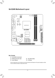
The box contents are for reference only and the actual items shall depend on the product package you obtain. GA-E240N Motherboard Layout CI KB_MS ATX_12V CPU_FAN iTE Super I/O B_BIOS M_BIOS VGA COM LPT AMD E-240 APU GA-E240N USB_HDMI F_USB2 USB_LAN SPDIF_O AUDIO Realtek F_USB1 GbE LAN BAT F_AUDIO CODEC PCI AMD A45 FCH SATA2 0 1 2 3 DDR3_0 DDR3_1 SYS_FAN ATX PWR_LED CLR_CMOS F_PANEL Box Contents 55 GA-E240N motherboard 55 Motherboard driver disk 55 User's Manual 55 Two SATA cables 55 I/O Shield The box contents above are subject to change without notice. - 5 -
The box contents are for reference only and the actual items shall depend on the product package you obtain. GA-E240N Motherboard Layout CI KB_MS ATX_12V CPU_FAN iTE Super I/O B_BIOS M_BIOS VGA COM LPT AMD E-240 APU GA-E240N USB_HDMI F_USB2 USB_LAN SPDIF_O AUDIO Realtek F_USB1 GbE LAN BAT F_AUDIO CODEC PCI AMD A45 FCH SATA2 0 1 2 3 DDR3_0 DDR3_1 SYS_FAN ATX PWR_LED CLR_CMOS F_PANEL Box Contents 55 GA-E240N motherboard 55 Motherboard driver disk 55 User's Manual 55 Two SATA cables 55 I/O Shield The box contents above are subject to change without notice. - 5 -
Manual
Page 12
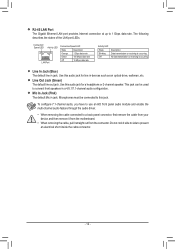
... rate. To configure 7.1-channel audio, you have to use an HD front panel audio module and enable the multi-channel audio feature through the audio driver. •• When removing the cable connected to prevent an electrical short inside the cable connector. - 12 - Use this audio jack for a ... Do not rock it side to side to a back panel connector, first remove the cable from your device and then remove it from the motherboard. •• When removing the cable, pull it straight out from the connector. Microphones must be used to connect front speakers in devices such...
... rate. To configure 7.1-channel audio, you have to use an HD front panel audio module and enable the multi-channel audio feature through the audio driver. •• When removing the cable connected to prevent an electrical short inside the cable connector. - 12 - Use this audio jack for a ... Do not rock it side to side to a back panel connector, first remove the cable from your device and then remove it from the motherboard. •• When removing the cable, pull it straight out from the connector. Microphones must be used to connect front speakers in devices such...
Manual
Page 29
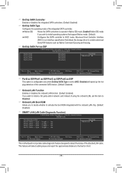
...Select F5: Previous Values +/-/PU/PD: Value F10: Save F6: Fail-Safe Defaults ESC: Exit F1: General Help F7: Optimized Defaults This motherboard incorporates cable diagnostic feature designed to AHCI mode. Enabled Native IDE mode if you to decide whether to operate in Native IDE mode. Advanced Host...the onboard LAN, set this item to Disabled. && Onboard LAN Boot ROM Allows you wish to install operating systems that allows the storage driver to enable advanced Serial ATA features such as Native Command Queuing and hot plug. && OnChip SATA Port as ESP CMOS Setup Utility-Copyright ...
...Select F5: Previous Values +/-/PU/PD: Value F10: Save F6: Fail-Safe Defaults ESC: Exit F1: General Help F7: Optimized Defaults This motherboard incorporates cable diagnostic feature designed to AHCI mode. Enabled Native IDE mode if you to decide whether to operate in Native IDE mode. Advanced Host...the onboard LAN, set this item to Disabled. && Onboard LAN Boot ROM Allows you wish to install operating systems that allows the storage driver to enable advanced Serial ATA features such as Native Command Queuing and hot plug. && OnChip SATA Port as ESP CMOS Setup Utility-Copyright ...
Manual
Page 35
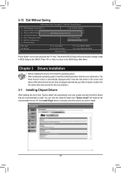
... BIOS F12: Load CMOS from BIOS Press on this item and press the key. Chapter 3 Drivers Installation •• Before installing the drivers, first install the operating system. •• After installing the operating system, insert the motherboard driver disk into your system and then list all Data F11: Save CMOS to My Computer...
... BIOS F12: Load CMOS from BIOS Press on this item and press the key. Chapter 3 Drivers Installation •• Before installing the drivers, first install the operating system. •• After installing the operating system, insert the motherboard driver disk into your system and then list all Data F11: Save CMOS to My Computer...


