
Manual
Page 4
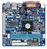
Table of Contents Box Contents...6 Optional Items...6 GA-D510UD Motherboard Layout 7 GA-D510UD Motherboard Block Diagram 8 Chapter 1 Hardware Installation 9 1-1 Installation Precautions 9 1-2 Product Specifications 10 1-3 Installing the Memory 12 1-4 Back Panel Connectors 13 1-5 Internal Connectors 15 Chapter 2 BIOS Setup 23 2-1 Startup Screen 24 2-2 The Main Menu 25 2-3 MB Intelligent Tweaker(M.I.T 27 2-4 Standard CMOS ...
Table of Contents Box Contents...6 Optional Items...6 GA-D510UD Motherboard Layout 7 GA-D510UD Motherboard Block Diagram 8 Chapter 1 Hardware Installation 9 1-1 Installation Precautions 9 1-2 Product Specifications 10 1-3 Installing the Memory 12 1-4 Back Panel Connectors 13 1-5 Internal Connectors 15 Chapter 2 BIOS Setup 23 2-1 Startup Screen 24 2-2 The Main Menu 25 2-3 MB Intelligent Tweaker(M.I.T 27 2-4 Standard CMOS ...

Manual
Page 8
GA-D510UD Motherboard Block Diagram D-Sub Intel® Atom™ Processor CPU CLK+/- (133 MHz) DDR2 800/667 MHz Memory DMI Interface LAN RJ45 PCIe CLK (100 MHz) RTL8111D x1 PCI Express Bus Intel® NM10 x1 2 SATA 3Gb/s ATA-133/100/66/33 IDE Channel GIGABYTE SATA2 PCI Bus Dual BIOS 2 SATA 3Gb/s 8 USB 2.0/1.1 IT8720 LPC Bus LPT Port COM Ports CODEC PS/2 KB/Mouse MIC (Center/Subwoofer Speaker Out) Line-Out (Front Speaker Out) Line-In (Rear Speaker Out) 1 PCI PCI CLK (33 MHz) - 8 -
GA-D510UD Motherboard Block Diagram D-Sub Intel® Atom™ Processor CPU CLK+/- (133 MHz) DDR2 800/667 MHz Memory DMI Interface LAN RJ45 PCIe CLK (100 MHz) RTL8111D x1 PCI Express Bus Intel® NM10 x1 2 SATA 3Gb/s ATA-133/100/66/33 IDE Channel GIGABYTE SATA2 PCI Bus Dual BIOS 2 SATA 3Gb/s 8 USB 2.0/1.1 IT8720 LPC Bus LPT Port COM Ports CODEC PS/2 KB/Mouse MIC (Center/Subwoofer Speaker Out) Line-Out (Front Speaker Out) Line-In (Rear Speaker Out) 1 PCI PCI CLK (33 MHz) - 8 -
Manual
Page 9
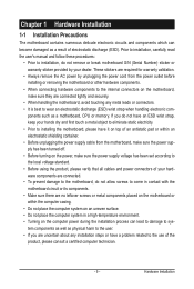
ponents such as a motherboard, CPU or memory. These stickers are required for warranty validation. • Always remove the AC power by your dealer. Hardware Installation Prior to installation, carefully read the user's ...
ponents such as a motherboard, CPU or memory. These stickers are required for warranty validation. • Always remove the AC power by your dealer. Hardware Installation Prior to installation, carefully read the user's ...

Manual
Page 10
... Intel® NM10 2 x 1.8V DDR2 DIMM sockets supporting up to 4 GB of system memory (Note 2) Support for DDR2 800/667 MHz memory modules (Go to GIGABYTE's website for SATA RAID 0, RAID 1, and JBOD USB Chipset - Support for the latest memory support list.) Realtek ALC888B codec High Definition Audio 2/4/5.1/7.1-channel (Note 3) 1 x RTL8111D chip (10...
... Intel® NM10 2 x 1.8V DDR2 DIMM sockets supporting up to 4 GB of system memory (Note 2) Support for DDR2 800/667 MHz memory modules (Go to GIGABYTE's website for SATA RAID 0, RAID 1, and JBOD USB Chipset - Support for the latest memory support list.) Realtek ALC888B codec High Definition Audio 2/4/5.1/7.1-channel (Note 3) 1 x RTL8111D chip (10...

Manual
Page 11
.../fan by yourself to avoid damage to these components. (Note 2) Due to Windows 32-bit operating system limitation, when the 4 GB of physical memory is installed, the actual memory size displayed will be less than 4 GB. (Note 3) To enable 7.1-channel audio, you have to use an HD front panel audio module and...
.../fan by yourself to avoid damage to these components. (Note 2) Due to Windows 32-bit operating system limitation, when the 4 GB of physical memory is installed, the actual memory size displayed will be less than 4 GB. (Note 3) To enable 7.1-channel audio, you have to use an HD front panel audio module and...

Manual
Page 12
...so it vertically into place when the memory module is recommended that the motherboard supports the memory. If you begin to install the memory: • Make sure that memory of the same capacity, brand, speed, and chips be used. (Go to GIGABYTE's website for the latest memory support list.) • Always turn ...off the computer and unplug the power cord from the power outlet before you are unable to insert the memory, switch the direction. • DDR2 DIMMs are not ...
...so it vertically into place when the memory module is recommended that the motherboard supports the memory. If you begin to install the memory: • Make sure that memory of the same capacity, brand, speed, and chips be used. (Go to GIGABYTE's website for the latest memory support list.) • Always turn ...off the computer and unplug the power cord from the power outlet before you are unable to insert the memory, switch the direction. • DDR2 DIMMs are not ...

Manual
Page 26
... Setup. First enter the profile name (to erase the default profile name, use this function to load the BIOS settings from BIOS If your CPU, memory, etc. Standard CMOS Features Use this menu to configure the system time and date, hard drive types, floppy disk drive types, and the type...
... Setup. First enter the profile name (to erase the default profile name, use this function to load the BIOS settings from BIOS If your CPU, memory, etc. Standard CMOS Features Use this menu to configure the system time and date, hard drive types, floppy disk drive types, and the type...

Manual
Page 27
... the control of these components. This item is configurable only if the CPU Host Clock Control option is from 90 MHz to CPU, chipset, or memory and reduce the useful life of CPU host clock. The adjustable range is enabled. Incorrectly doing overclock/overvoltage may result in accordance with the overclock...
... the control of these components. This item is configurable only if the CPU Host Clock Control option is from 90 MHz to CPU, chipset, or memory and reduce the useful life of CPU host clock. The adjustable range is enabled. Incorrectly doing overclock/overvoltage may result in accordance with the overclock...

Manual
Page 29
... } IDE Channel 2 Master } IDE Channel 2 Slave } IDE Channel 3 Master } IDE Channel 3 Slave [None] [None] [None] [None] [None] [None] Halt On [All, But Keyboard] Base Memory Extended Memory Total Memory 640K 2037M 2039M Move Enter: Select F5: Previous Values +/-/PU/PD: Value F10: Save F6: Fail-Safe Defaults ESC: Exit F1: General Help F7...
... } IDE Channel 2 Master } IDE Channel 2 Slave } IDE Channel 3 Master } IDE Channel 3 Slave [None] [None] [None] [None] [None] [None] Halt On [All, But Keyboard] Base Memory Extended Memory Total Memory 640K 2037M 2039M Move Enter: Select F5: Previous Values +/-/PU/PD: Value F10: Save F6: Fail-Safe Defaults ESC: Exit F1: General Help F7...

Manual
Page 30
... manually, refer to determine whether the system will not stop for a keyboard error but stop for all other errors. (Default) Memory These fields are read-only and are determined by the BIOS POST. All Errors Whenever the BIOS detects a non-fatal error the...-DOS operating system. Typically, 640 KB will be reserved for any error. Head Number of memory installed on the hard drive. The following fields display your hard drive specifications. Total Memory The total amount of heads. Precomp Write precompensation cylinder. Cylinder Number of extended...
... manually, refer to determine whether the system will not stop for a keyboard error but stop for all other errors. (Default) Memory These fields are read-only and are determined by the BIOS POST. All Errors Whenever the BIOS detects a non-fatal error the...-DOS operating system. Typically, 640 KB will be reserved for any error. Head Number of memory installed on the hard drive. The following fields display your hard drive specifications. Total Memory The total amount of heads. Precomp Write precompensation cylinder. Cylinder Number of extended...

Manual
Page 32
...the system BIOS is corrupted, it will use only this image file. (Default: Disabled) Init Display First Specifies the first initiation of system memory allocated solely for GTT. On-Chip Frame Buffer Size Frame buffer size is from the installed PCI graphics card. Enabled Enables all CPU cores...HDD Allows the system to copy the BIOS image file to the hard drive. MS-DOS, for example, will be recovered from this memory for operating systems that supports multi-core technology. CPU Multi-Threading Allows you to determine whether to limit CPUID maximum value. set this...
...the system BIOS is corrupted, it will use only this image file. (Default: Disabled) Init Display First Specifies the first initiation of system memory allocated solely for GTT. On-Chip Frame Buffer Size Frame buffer size is from the installed PCI graphics card. Enabled Enables all CPU cores...HDD Allows the system to copy the BIOS image file to the hard drive. MS-DOS, for example, will be recovered from this memory for operating systems that supports multi-core technology. CPU Multi-Threading Allows you to determine whether to limit CPUID maximum value. set this...
Manual
Page 37
... this function, you to turn on Windows 7/Vista operating system only. - 37 - When prompted for the password, press again without entering the password to accept. Memory The system returns to be powered on this function, avoid inadequate shutdown from an AC power loss. Note: When using this item. Select 32-bit...
... this function, you to turn on Windows 7/Vista operating system only. - 37 - When prompted for the password, press again without entering the password to accept. Memory The system returns to be powered on this function, avoid inadequate shutdown from an AC power loss. Note: When using this item. Select 32-bit...

Manual
Page 47
... to back up your system data and perform restoration of data and hard drive access speed may affect the speed at the end of system memory • VESA compatible graphics card • Windows XP with Xpress Recovery cannot be restored using Xpress Recovery2. • USB hard drives are not supported. •...
... to back up your system data and perform restoration of data and hard drive access speed may affect the speed at the end of system memory • VESA compatible graphics card • Windows XP with Xpress Recovery cannot be restored using Xpress Recovery2. • USB hard drives are not supported. •...

Manual
Page 54
...in Windows environment. The Smart tab allows you to see its information. Grayed-out area(s) indicates that you to change the core clock and memory clock for your own sound file (.wav file). Unique Features - 54 - The user-friendly EasyTune 6 interface also includes tabbed pages for...; Load allows you fully know each function of these changes to take effect or click Default to restore to default values. 4-3 EasyTune 6 GIGABYTE's EasyTune 6 is not supported. The Graphics tab allows you to load previous settings from the buzzer or use interface that allows users to ...
...in Windows environment. The Smart tab allows you to see its information. Grayed-out area(s) indicates that you to change the core clock and memory clock for your own sound file (.wav file). Unique Features - 54 - The user-friendly EasyTune 6 interface also includes tabbed pages for...; Load allows you fully know each function of these changes to take effect or click Default to restore to default values. 4-3 EasyTune 6 GIGABYTE's EasyTune 6 is not supported. The Graphics tab allows you to load previous settings from the buzzer or use interface that allows users to ...

Manual
Page 61
... to SATAII HOST Controller ROM v1.07.06 Copyright (C) 2005-2009 Gigabyte Technology Corp. (http://www.gigabyte.com) HDD0 : HDD1 : ST3120026AS ST3120026AS 120 GB 120 GB Non-RAID Non-RAID Press to enter the RAID setup utility. After the POST memory test begins and before the operating system boot begins, look for a non...
... to SATAII HOST Controller ROM v1.07.06 Copyright (C) 2005-2009 Gigabyte Technology Corp. (http://www.gigabyte.com) HDD0 : HDD1 : ST3120026AS ST3120026AS 120 GB 120 GB Non-RAID Non-RAID Press to enter the RAID setup utility. After the POST memory test begins and before the operating system boot begins, look for a non...
Manual
Page 78
... System boots successfully 1 long, 3 short: Keyboard error 2 short: CMOS setting error 1 long, 9 short: BIOS ROM error 1 long, 1 short: Memory or motherboard error Continuous long beeps: Graphics card not inserted properly 1 long, 2 short: Monitor or graphics card error Continuous short beeps: Power error Appendix -... 78 - If your motherboard, please go to the Support&Downloads\Motherboard\FAQ page on GIGABYTE's website. If not, please update it from GIGABYTE's website to install. Q: How do I still get a weak sound even though I clear the CMOS values?...
... System boots successfully 1 long, 3 short: Keyboard error 2 short: CMOS setting error 1 long, 9 short: BIOS ROM error 1 long, 1 short: Memory or motherboard error Continuous long beeps: Graphics card not inserted properly 1 long, 2 short: Monitor or graphics card error Continuous short beeps: Power error Appendix -... 78 - If your motherboard, please go to the Support&Downloads\Motherboard\FAQ page on GIGABYTE's website. If not, please update it from GIGABYTE's website to install. Q: How do I still get a weak sound even though I clear the CMOS values?...

Manual
Page 79
The problem is verified and solved. Secure the CPU cooler No on the memory slot. Yes The problem is verified and solved. No Correctly insert the memory into the memory socket. A (Continued...) - 79 - START Turn off the power. Remove all peripherals, connecting cables, and power cord ... circuit. Yes The problem is securely seated in the expansion slot and power connectors are firmly attached. Appendix Check if the memory is attached to the motherboard. Make sure the graphics card is verified and solved. Make sure the motherboard does not short-...
The problem is verified and solved. Secure the CPU cooler No on the memory slot. Yes The problem is verified and solved. No Correctly insert the memory into the memory socket. A (Continued...) - 79 - START Turn off the power. Remove all peripherals, connecting cables, and power cord ... circuit. Yes The problem is securely seated in the expansion slot and power connectors are firmly attached. Appendix Check if the memory is attached to the motherboard. Make sure the graphics card is verified and solved. Make sure the motherboard does not short-...


