

Manual
Page 4
Table of Contents Box Contents...6 Optional Items...6 GA-D525TUD/GA-D425TUD Motherboard Layout 7 GA-D525TUD/GA-D425TUD Motherboard Block Diagram 8 Chapter 1 Hardware Installation 9 1-1 Installation Precautions 9 1-2 Product Specifications 10 1-3 Installing the Memory 12 1-4 Back Panel Connectors 13 1-5 Internal Connectors 15 Chapter 2 BIOS Setup 23 2-1 Startup Screen 24 2-2 The Main Menu 25 2-3 MB Intelligent Tweaker(M.I.T 27 2-4 Standard CMOS ...
Table of Contents Box Contents...6 Optional Items...6 GA-D525TUD/GA-D425TUD Motherboard Layout 7 GA-D525TUD/GA-D425TUD Motherboard Block Diagram 8 Chapter 1 Hardware Installation 9 1-1 Installation Precautions 9 1-2 Product Specifications 10 1-3 Installing the Memory 12 1-4 Back Panel Connectors 13 1-5 Internal Connectors 15 Chapter 2 BIOS Setup 23 2-1 Startup Screen 24 2-2 The Main Menu 25 2-3 MB Intelligent Tweaker(M.I.T 27 2-4 Standard CMOS ...

Manual
Page 8
GA-D525TUD/GA-D425TUD Motherboard Block Diagram D-Sub Intel® Atom™ CPU CPU CLK+/- (200 MHz) DDR3 800 MHz Memory DMI Interface LAN RJ45 PCIe CLK (100 MHz) Realtek RTL8111E x1 PCI Express Bus Intel® NM10 x1 2 SATA 3Gb/s ATA-133/100/66/33 IDE Channel GIGABYTE SATA2 PCI Bus Dual BIOS 2 SATA 3Gb/s 8 USB 2.0/1.1 iTE LPC Bus IT8720 LPT Port COM Ports CODEC PS/2 KB/Mouse MIC (Center/Subwoofer Speaker Out) Line-Out (Front Speaker Out) Line-In (Rear Speaker Out) 1 PCI PCI CLK (33 MHz) - 8 -
GA-D525TUD/GA-D425TUD Motherboard Block Diagram D-Sub Intel® Atom™ CPU CPU CLK+/- (200 MHz) DDR3 800 MHz Memory DMI Interface LAN RJ45 PCIe CLK (100 MHz) Realtek RTL8111E x1 PCI Express Bus Intel® NM10 x1 2 SATA 3Gb/s ATA-133/100/66/33 IDE Channel GIGABYTE SATA2 PCI Bus Dual BIOS 2 SATA 3Gb/s 8 USB 2.0/1.1 iTE LPC Bus IT8720 LPT Port COM Ports CODEC PS/2 KB/Mouse MIC (Center/Subwoofer Speaker Out) Line-Out (Front Speaker Out) Line-In (Rear Speaker Out) 1 PCI PCI CLK (33 MHz) - 8 -

Manual
Page 9
... connectors. • It is best to wear an electrostatic discharge (ESD) wrist strap when handling electronic com- Hardware Installation ponents such as a motherboard, CPU or memory. Chapter 1 Hardware Installation 1-1 Installation Precautions The motherboard contains numerous delicate electronic circuits and components which can lead to damage to system components as well as...
... connectors. • It is best to wear an electrostatic discharge (ESD) wrist strap when handling electronic com- Hardware Installation ponents such as a motherboard, CPU or memory. Chapter 1 Hardware Installation 1-1 Installation Precautions The motherboard contains numerous delicate electronic circuits and components which can lead to damage to system components as well as...
Manual
Page 10
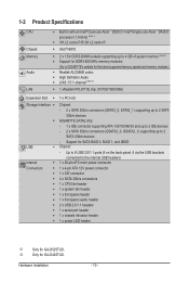
...for GA-D425TUD. Up to 8 USB 2.0/1.1 ports (4 on the back panel, 4 via the USB brackets connected to 2 SATA 3Gb/s devices - k Only for SATA RAID 0, RAID 1, and JBOD USB Chipset: - Hardware Installation - 10 - 1-2 Product Specifications CPU Chipset Memory ...5V DDR3 DIMM sockets supporting up to 4 GB of system memory (Note 2) Support for DDR3 800 MHz memory modules (Go to GIGABYTE's website for the latest supported memory speeds and memory modules.) Realtek ALC888B codec High Definition Audio 2/4/5.1/7.1-channel (Note 3)...
...for GA-D425TUD. Up to 8 USB 2.0/1.1 ports (4 on the back panel, 4 via the USB brackets connected to 2 SATA 3Gb/s devices - k Only for SATA RAID 0, RAID 1, and JBOD USB Chipset: - Hardware Installation - 10 - 1-2 Product Specifications CPU Chipset Memory ...5V DDR3 DIMM sockets supporting up to 4 GB of system memory (Note 2) Support for DDR3 800 MHz memory modules (Go to GIGABYTE's website for the latest supported memory speeds and memory modules.) Realtek ALC888B codec High Definition Audio 2/4/5.1/7.1-channel (Note 3)...

Manual
Page 11
.../fan by yourself to avoid damage to these components. (Note 2) Due to Windows 32-bit operating system limitation, when the 4 GB of physical memory is installed, the actual memory size displayed will be less than 4 GB. (Note 3) To enable 7.1-channel audio, you have to use an HD front panel audio module and...
.../fan by yourself to avoid damage to these components. (Note 2) Due to Windows 32-bit operating system limitation, when the 4 GB of physical memory is installed, the actual memory size displayed will be less than 4 GB. (Note 3) To enable 7.1-channel audio, you have to use an HD front panel audio module and...
Manual
Page 12
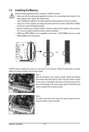
Step 1: Note the orientation of the socket will snap into the memory socket. Step 2: The clips at both ends of the memory module. Hardware Installation - 12 - A memory module can be used. (Go to GIGABYTE's website for the latest supported memory speeds and memory modules.) • Always turn off the computer and unplug the power cord from the...
Step 1: Note the orientation of the socket will snap into the memory socket. Step 2: The clips at both ends of the memory module. Hardware Installation - 12 - A memory module can be used. (Go to GIGABYTE's website for the latest supported memory speeds and memory modules.) • Always turn off the computer and unplug the power cord from the...
Manual
Page 26
... system becomes unstable and you have loaded the BIOS default settings, you to restrict access to load the BIOS settings from BIOS If your CPU, memory, etc. Standard CMOS Features Use this menu to configure the system time and date, hard drive types, floppy disk drive types, and the type...
... system becomes unstable and you have loaded the BIOS default settings, you to restrict access to load the BIOS settings from BIOS If your CPU, memory, etc. Standard CMOS Features Use this menu to configure the system time and date, hard drive types, floppy disk drive types, and the type...
Manual
Page 27
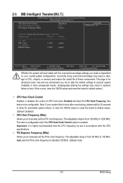
... with the CPU specifications. Note: If your overall system configurations. If this occurs, clear the CMOS values and reset the board to CPU, chipset, or memory and reduce the useful life of CPU host clock. 2-3 MB Intelligent Tweaker(M.I.T.) CMOS Setup Utility-Copyright (C) 1984-2010 Award Software MB Intelligent Tweaker(M.I.T.) CPU Host...
... with the CPU specifications. Note: If your overall system configurations. If this occurs, clear the CMOS values and reset the board to CPU, chipset, or memory and reduce the useful life of CPU host clock. 2-3 MB Intelligent Tweaker(M.I.T.) CMOS Setup Utility-Copyright (C) 1984-2010 Award Software MB Intelligent Tweaker(M.I.T.) CPU Host...

Manual
Page 29
... } IDE Channel 2 Master } IDE Channel 2 Slave } IDE Channel 3 Master } IDE Channel 3 Slave [None] [None] [None] [None] [None] [None] Halt On [All, But Keyboard] Base Memory Extended Memory Total Memory 640K 2037M 2039M Move Enter: Select F5: Previous Values +/-/PU/PD: Value F10: Save F6: Fail-Safe Defaults ESC: Exit F1: General Help F7...
... } IDE Channel 2 Master } IDE Channel 2 Slave } IDE Channel 3 Master } IDE Channel 3 Slave [None] [None] [None] [None] [None] [None] Halt On [All, But Keyboard] Base Memory Extended Memory Total Memory 640K 2037M 2039M Move Enter: Select F5: Previous Values +/-/PU/PD: Value F10: Save F6: Fail-Safe Defaults ESC: Exit F1: General Help F7...
Manual
Page 30
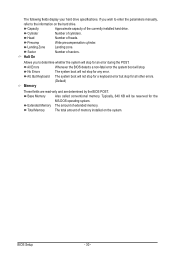
... manually, refer to determine whether the system will stop . No Errors The system boot will stop for all other errors. (Default) Memory These fields are read-only and are determined by the BIOS POST. All Errors Whenever the BIOS detects a non-fatal error the system...not stop for an error during the POST. All, But Keyboard The system boot will be reserved for any error. Base Memory Also called conventional memory. Total Memory The total amount of sectors. Cylinder Number of the currently installed hard drive. Typically, 640 KB will not stop for a...
... manually, refer to determine whether the system will stop . No Errors The system boot will stop for all other errors. (Default) Memory These fields are read-only and are determined by the BIOS POST. All Errors Whenever the BIOS detects a non-fatal error the system...not stop for an error during the POST. All, But Keyboard The system boot will be reserved for any error. Base Memory Also called conventional memory. Total Memory The total amount of sectors. Cylinder Number of the currently installed hard drive. Typically, 640 KB will not stop for a...

Manual
Page 32
...+1 for GTT (default), 1MB+1 for display. to 3 Allows you to set this image file. (Default: Disabled) Init Display First Specifies the first initiation of system memory allocated solely for the onboard graphics controller. This feature only works for the BIOS to limit CPUID maximum value. Enabled Enables all CPU cores and... the first display. MS-DOS, for example, will be recovered from this item to Enabled for Windows XP operating system; BIOS Setup - 32 - Set this memory for GTT.
...+1 for GTT (default), 1MB+1 for display. to 3 Allows you to set this image file. (Default: Disabled) Init Display First Specifies the first initiation of system memory allocated solely for the onboard graphics controller. This feature only works for the BIOS to limit CPUID maximum value. Enabled Enables all CPU cores and... the first display. MS-DOS, for example, will be recovered from this item to Enabled for Windows XP operating system; BIOS Setup - 32 - Set this memory for GTT.

Manual
Page 37
... system to be turned on by a PS/2 mouse wake-up , power on by mouse, power on Windows 7/Vista operating system only. - 37 - Press on automatically. Memory The system returns to accept.
... system to be turned on by a PS/2 mouse wake-up , power on by mouse, power on Windows 7/Vista operating system only. - 37 - Press on automatically. Memory The system returns to accept.

Manual
Page 47
... to back up a hard drive than to the first and second SATA connectors, the hard drive on your system data and perform restoration of system memory • VESA compatible graphics card • Windows XP with Xpress Recovery cannot be restored using Xpress Recovery2. • USB hard drives are not supported. •...
... to back up a hard drive than to the first and second SATA connectors, the hard drive on your system data and perform restoration of system memory • VESA compatible graphics card • Windows XP with Xpress Recovery cannot be restored using Xpress Recovery2. • USB hard drives are not supported. •...

Manual
Page 54
... your own sound file (.wav file). The EasyTune 6 Interface Tabs Information Tab Function The CPU tab provides information on the installed memory module(s). Available functions in EasyTune 6 may result in Windows environment. Unique Features - 54 - Before you fully know each function ... for CPU and memory information, letting users read their system settings or do the overclock/overvoltage, make sure that the item is not configurable or the function is not supported. 4-3 EasyTune 6 GIGABYTE's EasyTune 6 is a simple and easy-to-use your ATI or NVIDIA...
... your own sound file (.wav file). The EasyTune 6 Interface Tabs Information Tab Function The CPU tab provides information on the installed memory module(s). Available functions in EasyTune 6 may result in Windows environment. Unique Features - 54 - Before you fully know each function ... for CPU and memory information, letting users read their system settings or do the overclock/overvoltage, make sure that the item is not configurable or the function is not supported. 4-3 EasyTune 6 GIGABYTE's EasyTune 6 is a simple and easy-to-use your ATI or NVIDIA...

Manual
Page 61
...press to configure a RAID array. PCI Express to SATAII HOST Controller ROM v1.07.06 Copyright (C) 2005-2009 Gigabyte Technology Corp. (http://www.gigabyte.com) HDD0 : HDD1 : ST3120026AS ST3120026AS 120 GB 120 GB Non-RAID Non-RAID Press to enter RAID Setup Utility..." (Figure 2). Gigabyte Technology Corp. GIGABYTE Technology Corp. Figure 2 In the main screen of Windows operating system for a message which says "Press to enter RAID Setup Utility ... After the POST memory test begins and before the operating system boot begins,...
...press to configure a RAID array. PCI Express to SATAII HOST Controller ROM v1.07.06 Copyright (C) 2005-2009 Gigabyte Technology Corp. (http://www.gigabyte.com) HDD0 : HDD1 : ST3120026AS ST3120026AS 120 GB 120 GB Non-RAID Non-RAID Press to enter RAID Setup Utility..." (Figure 2). Gigabyte Technology Corp. GIGABYTE Technology Corp. Figure 2 In the main screen of Windows operating system for a message which says "Press to enter RAID Setup Utility ... After the POST memory test begins and before the operating system boot begins,...

Manual
Page 78
...System boots successfully 1 long, 3 short: Keyboard error 2 short: CMOS setting error 1 long, 9 short: BIOS ROM error 1 long, 1 short: Memory or motherboard error Continuous long beeps: Graphics card not inserted properly 1 long, 2 short: Monitor or graphics card error Continuous short beeps: Power error Appendix ..., click Cancel. 5-3 Troubleshooting 5-3-1 Frequently Asked Questions To read more details, go to the Support&Downloads\Motherboard\FAQ page on GIGABYTE's website. Q: How do the beeps emitted during the POST. If your motherboard, please go to clear the CMOS values....
...System boots successfully 1 long, 3 short: Keyboard error 2 short: CMOS setting error 1 long, 9 short: BIOS ROM error 1 long, 1 short: Memory or motherboard error Continuous long beeps: Graphics card not inserted properly 1 long, 2 short: Monitor or graphics card error Continuous short beeps: Power error Appendix ..., click Cancel. 5-3 Troubleshooting 5-3-1 Frequently Asked Questions To read more details, go to the Support&Downloads\Motherboard\FAQ page on GIGABYTE's website. Q: How do the beeps emitted during the POST. If your motherboard, please go to clear the CMOS values....
Manual
Page 79
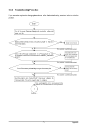
... (Continued...) - 79 - Appendix The problem is verified and solved. Connect the CPU cooler power cable to start the computer. Check if the memory is securely seated in the expansion slot and power connectors are firmly attached. Make sure the graphics card is installed properly on the CPU. Is... cable. Make sure the motherboard does not short-circuit with the chassis or other metal objects. Secure the CPU cooler No on the memory slot. No Check if the CPU cooler is verified and solved. START Turn off the power. Remove all peripherals, connecting cables, and...
... (Continued...) - 79 - Appendix The problem is verified and solved. Connect the CPU cooler power cable to start the computer. Check if the memory is securely seated in the expansion slot and power connectors are firmly attached. Make sure the graphics card is installed properly on the CPU. Is... cable. Make sure the motherboard does not short-circuit with the chassis or other metal objects. Secure the CPU cooler No on the memory slot. No Check if the CPU cooler is verified and solved. START Turn off the power. Remove all peripherals, connecting cables, and...


