
Manual
Page 3
... read the User's Manual. For instructions on your motherboard revision before updating motherboard BIOS, drivers, or when looking for technical information. Example: No part of GIGABYTE. The trademarks mentioned in this manual are legally registered to the specifications and features in this...translated, transmitted, or published in any form or by copyright laws and is 1.0. Disclaimer Information in the use GIGABYTE's unique features, read or download the information on/from the Support&Downloads\Motherboard\Technology Guide page on our website. All rights ...
... read the User's Manual. For instructions on your motherboard revision before updating motherboard BIOS, drivers, or when looking for technical information. Example: No part of GIGABYTE. The trademarks mentioned in this manual are legally registered to the specifications and features in this...translated, transmitted, or published in any form or by copyright laws and is 1.0. Disclaimer Information in the use GIGABYTE's unique features, read or download the information on/from the Support&Downloads\Motherboard\Technology Guide page on our website. All rights ...

Manual
Page 4
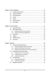
Table of Contents Box Contents...6 Optional Items...6 GA-D525TUD/GA-D425TUD Motherboard Layout 7 GA-D525TUD/GA-D425TUD Motherboard Block Diagram 8 Chapter 1 Hardware Installation 9 1-1 Installation Precautions 9 1-2 Product Specifications 10 1-3 Installing the Memory 12 1-4 Back Panel Connectors 13 1-5 Internal Connectors 15 Chapter 2 BIOS Setup 23 2-1 Startup Screen 24 2-2 The Main Menu 25 2-3 MB Intelligent Tweaker(M.I.T 27 2-4 Standard CMOS Features 29...
Table of Contents Box Contents...6 Optional Items...6 GA-D525TUD/GA-D425TUD Motherboard Layout 7 GA-D525TUD/GA-D425TUD Motherboard Block Diagram 8 Chapter 1 Hardware Installation 9 1-1 Installation Precautions 9 1-2 Product Specifications 10 1-3 Installing the Memory 12 1-4 Back Panel Connectors 13 1-5 Internal Connectors 15 Chapter 2 BIOS Setup 23 2-1 Startup Screen 24 2-2 The Main Menu 25 2-3 MB Intelligent Tweaker(M.I.T 27 2-4 Standard CMOS Features 29...
Manual
Page 5
...Download Center 46 3-7 New Utilities...46 Chapter 4 Unique Features 47 4-1 Xpress Recovery2 47 4-2 BIOS Update Utilities 50 4-2-1 Updating the BIOS with the Q-Flash Utility 50 4-2-2 Updating the BIOS with the @BIOS Utility 53 4-3 EasyTune 6...54 4-4 Q-Share...55 4-5 SMART Recovery 56 4-6 Auto Green...57... Chapter 5 Appendix...59 5-1 Configuring SATA Hard Drive(s 59 5-1-1 Configuring GIGABYTE SATA2 SATA Controller 60 5-1-2 Making a SATA...
...Download Center 46 3-7 New Utilities...46 Chapter 4 Unique Features 47 4-1 Xpress Recovery2 47 4-2 BIOS Update Utilities 50 4-2-1 Updating the BIOS with the Q-Flash Utility 50 4-2-2 Updating the BIOS with the @BIOS Utility 53 4-3 EasyTune 6...54 4-4 Q-Share...55 4-5 SMART Recovery 56 4-6 Auto Green...57... Chapter 5 Appendix...59 5-1 Configuring SATA Hard Drive(s 59 5-1-1 Configuring GIGABYTE SATA2 SATA Controller 60 5-1-2 Making a SATA...

Manual
Page 8
GA-D525TUD/GA-D425TUD Motherboard Block Diagram D-Sub Intel® Atom™ CPU CPU CLK+/- (200 MHz) DDR3 800 MHz Memory DMI Interface LAN RJ45 PCIe CLK (100 MHz) Realtek RTL8111E x1 PCI Express Bus Intel® NM10 x1 2 SATA 3Gb/s ATA-133/100/66/33 IDE Channel GIGABYTE SATA2 PCI Bus Dual BIOS 2 SATA 3Gb/s 8 USB 2.0/1.1 iTE LPC Bus IT8720 LPT Port COM Ports CODEC PS/2 KB/Mouse MIC (Center/Subwoofer Speaker Out) Line-Out (Front Speaker Out) Line-In (Rear Speaker Out) 1 PCI PCI CLK (33 MHz) - 8 -
GA-D525TUD/GA-D425TUD Motherboard Block Diagram D-Sub Intel® Atom™ CPU CPU CLK+/- (200 MHz) DDR3 800 MHz Memory DMI Interface LAN RJ45 PCIe CLK (100 MHz) Realtek RTL8111E x1 PCI Express Bus Intel® NM10 x1 2 SATA 3Gb/s ATA-133/100/66/33 IDE Channel GIGABYTE SATA2 PCI Bus Dual BIOS 2 SATA 3Gb/s 8 USB 2.0/1.1 iTE LPC Bus IT8720 LPT Port COM Ports CODEC PS/2 KB/Mouse MIC (Center/Subwoofer Speaker Out) Line-Out (Front Speaker Out) Line-In (Rear Speaker Out) 1 PCI PCI CLK (33 MHz) - 8 -

Manual
Page 11
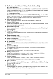
.../2 mouse port w 1 x parallel port w 1 x serial port w 1 x D-Sub port w 4 x USB 2.0/1.1 ports w 1 x RJ-45 port w 3 x audio jacks (Line In/Line Out/Microphone) w iTE IT8720 chip Hardware Monitor w w w w BIOS w w w w Unique Features w w w w w w w w w w w System voltage detection CPU temperature detection CPU/System fan speed detection CPU fan speed control 2 x 4 Mbit flash Use of licensed AWARD...
.../2 mouse port w 1 x parallel port w 1 x serial port w 1 x D-Sub port w 4 x USB 2.0/1.1 ports w 1 x RJ-45 port w 3 x audio jacks (Line In/Line Out/Microphone) w iTE IT8720 chip Hardware Monitor w w w w BIOS w w w w Unique Features w w w w w w w w w w w System voltage detection CPU temperature detection CPU/System fan speed detection CPU fan speed control 2 x 4 Mbit flash Use of licensed AWARD...

Manual
Page 19
... before replacing the battery. • Replace the battery with an equivalent one minute. (Or use a metal object like a screwdriver to keep the values (such as BIOS configurations, date, and time information) in the CMOS when the computer is operating. Pin No. You may be handled in the power cord and restart...
... before replacing the battery. • Replace the battery with an equivalent one minute. (Or use a metal object like a screwdriver to keep the values (such as BIOS configurations, date, and time information) in the CMOS when the computer is operating. Pin No. You may be handled in the power cord and restart...

Manual
Page 20
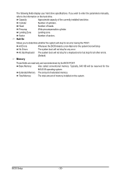
... the computer freezes and fails to the reset switch on the chassis front panel. When connecting your system using the power switch (refer to Chapter 2, "BIOS Setup," "Power Management Setup," for more information). • HD (Hard Drive Activity LED) Connects to the hard drive activity LED on the chassis front panel...
... the computer freezes and fails to the reset switch on the chassis front panel. When connecting your system using the power switch (refer to Chapter 2, "BIOS Setup," "Power Management Setup," for more information). • HD (Hard Drive Activity LED) Connects to the hard drive activity LED on the chassis front panel...

Manual
Page 23
...alter the default settings (unless you not flash the BIOS. When the power is a Windows-based utility that you need to) to keep the configuration values in the CMOS. To upgrade the BIOS, use either the GIGABYTE Q-Flash or @BIOS utility. • Q-Flash allows the user to ...quickly and easily upgrade or back up BIOS without entering the operating system. • @BIOS is turned off, the battery on . Inadequate BIOS flashing may result in system's failure...
...alter the default settings (unless you not flash the BIOS. When the power is a Windows-based utility that you need to) to keep the configuration values in the CMOS. To upgrade the BIOS, use either the GIGABYTE Q-Flash or @BIOS utility. • Q-Flash allows the user to ...quickly and easily upgrade or back up BIOS without entering the operating system. • @BIOS is turned off, the battery on . Inadequate BIOS flashing may result in system's failure...

Manual
Page 24
... Xpress Recovery2 during the POST. The system will still be used for one time only. Motherboard Model BIOS Version Award Modular BIOS v6.00PG, An Energy Star Ally Copyright (C) 1984-2010, Award Software, Inc. BIOS Setup - 24 - 2-1 Startup Screen The following screens may appear when the computer boots. For more... ever entered Xpress Recovery2 to back up arrow key or the down arrow key to select the first boot device, then press to enter BIOS Setup first. To exit Boot Menu, press . After system restart, the device boot order will directly boot from the device configured in ...
... Xpress Recovery2 during the POST. The system will still be used for one time only. Motherboard Model BIOS Version Award Modular BIOS v6.00PG, An Energy Star Ally Copyright (C) 1984-2010, Award Software, Inc. BIOS Setup - 24 - 2-1 Startup Screen The following screens may appear when the computer boots. For more... ever entered Xpress Recovery2 to back up arrow key or the down arrow key to select the first boot device, then press to enter BIOS Setup first. To exit Boot Menu, press . After system restart, the device boot order will directly boot from the device configured in ...

Manual
Page 25
...submenus Load the Fail-Safe BIOS default settings for the current submenus Load the Optimized BIOS default settings for the menu. Use arrow keys to move among the items and press to accept or enter a sub-menu. (Sample BIOS Version: GA-D525TUD E10c) CMOS Setup ...Utility-Copyright (C) 1984-2010 Award Software MB Intelligent Tweaker(M.I.T.) Standard CMOS Features Advanced BIOS Features Integrated Peripherals Power Management Setup ...
...submenus Load the Fail-Safe BIOS default settings for the current submenus Load the Optimized BIOS default settings for the menu. Use arrow keys to move among the items and press to accept or enter a sub-menu. (Sample BIOS Version: GA-D525TUD E10c) CMOS Setup ...Utility-Copyright (C) 1984-2010 Award Software MB Intelligent Tweaker(M.I.T.) Standard CMOS Features Advanced BIOS Features Integrated Peripherals Power Management Setup ...
Manual
Page 26
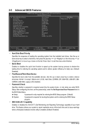
... time and date, hard drive types, floppy disk drive types, and the type of errors that stop the system boot, etc. Advanced BIOS Features Use this menu to configure the device boot order, advanced features available on the CPU, and the primary display adapter. Integrated Peripherals.... (Pressing can also carry out this menu to configure the clock, frequency and voltages of your system becomes unstable and you have loaded the BIOS default settings, you to make changes. Save & Exit Setup Save all changes and the previous settings remain in effect. The ...
... time and date, hard drive types, floppy disk drive types, and the type of errors that stop the system boot, etc. Advanced BIOS Features Use this menu to configure the device boot order, advanced features available on the CPU, and the primary display adapter. Integrated Peripherals.... (Pressing can also carry out this menu to configure the clock, frequency and voltages of your system becomes unstable and you have loaded the BIOS default settings, you to make changes. Save & Exit Setup Save all changes and the previous settings remain in effect. The ...
Manual
Page 27
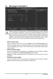
... to default values. (Default: Disabled) CPU Host Frequency (Mhz) Allows you to CPU, chipset, or memory and reduce the useful life of CPU host clock. BIOS Setup This page is highly recommended that the CPU frequency be configurable. The adjustable range is from 100 MHz to boot. Enabled will work stably...
... to default values. (Default: Disabled) CPU Host Frequency (Mhz) Allows you to CPU, chipset, or memory and reduce the useful life of CPU host clock. BIOS Setup This page is highly recommended that the CPU frequency be configurable. The adjustable range is from 100 MHz to boot. Enabled will work stably...

Manual
Page 28
******** Mother Board Voltage Control >>> CPU CPU Vcore The default is Auto. ******** >>> DRAM DRAM Voltage The default is Auto. BIOS Setup - 28 -
******** Mother Board Voltage Control >>> CPU CPU Vcore The default is Auto. ******** >>> DRAM DRAM Voltage The default is Auto. BIOS Setup - 28 -

Manual
Page 29
... None so the system will skip the detection of the device during the POST for faster system startup. • Auto Lets the BIOS automatically detect IDE/SATA devices during the POST for faster system startup. IDE Channel 2, 3 Master/Slave Extended IDE Drive Configure your ...Channel 0, 1 Master IDE Channel 0, 1 Master Configure your IDE/SATA devices by using one of the three methods below : • Auto Lets the BIOS automatically detect IDE/SATA devices during the POST. (Default) • None If no IDE/SATA devices are used , set this item to None so the...
... None so the system will skip the detection of the device during the POST for faster system startup. • Auto Lets the BIOS automatically detect IDE/SATA devices during the POST for faster system startup. IDE Channel 2, 3 Master/Slave Extended IDE Drive Configure your ...Channel 0, 1 Master IDE Channel 0, 1 Master Configure your IDE/SATA devices by using one of the three methods below : • Auto Lets the BIOS automatically detect IDE/SATA devices during the POST. (Default) • None If no IDE/SATA devices are used , set this item to None so the...
Manual
Page 30
...Write precompensation cylinder. Sector Number of extended memory. No Errors The system boot will be reserved for an error during the POST. BIOS Setup - 30 - Landing Zone Landing zone. Extended Memory The amount of sectors. If you to the information on the system.... determine whether the system will stop for all other errors. (Default) Memory These fields are read-only and are determined by the BIOS POST. Base Memory Also called conventional memory. Cylinder Number of heads. Total Memory The total amount of the currently installed hard drive....
...Write precompensation cylinder. Sector Number of extended memory. No Errors The system boot will be reserved for an error during the POST. BIOS Setup - 30 - Landing Zone Landing zone. Extended Memory The amount of sectors. If you to the information on the system.... determine whether the system will stop for all other errors. (Default) Memory These fields are read-only and are determined by the BIOS POST. Base Memory Also called conventional memory. Cylinder Number of heads. Total Memory The total amount of the currently installed hard drive....
Manual
Page 31
... device and press to issue warnings when a third party hardware monitor utility is required every time the system boots, or only when you enter BIOS Setup. After configuring this menu when finished. HDD S.M.A.R.T. Options are: LS120, Hard Disk, CDROM, ZIP, USB-FDD, USB-ZIP, USBCDROM, ...USB-HDD, Legacy LAN, Disabled. BIOS Setup Capability Enables or disables the S.M.A.R.T. (Self Monitoring and Reporting Technology) capability of your system to report read/write errors of loading the ...
... device and press to issue warnings when a third party hardware monitor utility is required every time the system boots, or only when you enter BIOS Setup. After configuring this menu when finished. HDD S.M.A.R.T. Options are: LS120, Hard Disk, CDROM, ZIP, USB-FDD, USB-ZIP, USBCDROM, ...USB-HDD, Legacy LAN, Disabled. BIOS Setup Capability Enables or disables the S.M.A.R.T. (Self Monitoring and Reporting Technology) capability of your system to report read/write errors of loading the ...

Manual
Page 32
...for GTT (default), 1MB+1 for Windows XP operating system; If the system BIOS is the total amount of the monitor display from 0 to 15 seconds. (Default: 0) Backup BIOS Image to HDD Allows the system to copy the BIOS image file to set this image file. (Default: Disabled) Init Display First ...Specifies the first initiation of system memory allocated solely for the BIOS to initialize the hard drive as the system boots up. Set this memory for operating systems that supports multi-core technology. This feature...
...for GTT (default), 1MB+1 for Windows XP operating system; If the system BIOS is the total amount of the monitor display from 0 to 15 seconds. (Default: 0) Backup BIOS Image to HDD Allows the system to copy the BIOS image file to set this image file. (Default: Disabled) Init Display First ...Specifies the first initiation of system memory allocated solely for the BIOS to initialize the hard drive as the system boots up. Set this memory for operating systems that supports multi-core technology. This feature...
Manual
Page 33
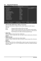
... function. (Default: Auto) If you wish to install a 3rd party add-in network card instead of using the onboard LAN, set this item to Disabled. BIOS Setup Onboard H/W LAN Enables or disables the onboard LAN function. (Default: Enabled) If you to decide whether to configure the SATA controllers integrated in the...
... function. (Default: Auto) If you wish to install a 3rd party add-in network card instead of using the onboard LAN, set this item to Disabled. BIOS Setup Onboard H/W LAN Enables or disables the onboard LAN function. (Default: Enabled) If you to decide whether to configure the SATA controllers integrated in the...

Manual
Page 34
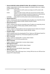
... length of wires will be the approximate distance to activate the boot ROM integrated with the onboard LAN chip. (Default: Disabled) Onboard SATA/IDE Device (GIGABYTE SATA2, IDE and GSATA2_0/1 Connectors) Enables or disables the IDE and SATA controllers integrated in the figure above. Note: The Gigabit hub will operate at... Open, and the length shown is attached to detect the status of the attached LAN cable. This feature will show 0m, as shown in the GIGABYTE SATA2 chip. (Default: Enabled) BIOS Setup - 34 - it will only operate at Port.....
... length of wires will be the approximate distance to activate the boot ROM integrated with the onboard LAN chip. (Default: Disabled) Onboard SATA/IDE Device (GIGABYTE SATA2, IDE and GSATA2_0/1 Connectors) Enables or disables the IDE and SATA controllers integrated in the figure above. Note: The Gigabit hub will operate at... Open, and the length shown is attached to detect the status of the attached LAN cable. This feature will show 0m, as shown in the GIGABYTE SATA2 chip. (Default: Enabled) BIOS Setup - 34 - it will only operate at Port.....
Manual
Page 35
...(Default: Disabled) USB Mouse Function Allows USB mouse to be used in MS-DOS. (Default: Disabled) USB Storage Function Determines whether to AHCI mode. BIOS Setup Options are : 378/IRQ7 (default), 278/IRQ5, 3BC/IRQ7, Disabled. Options are : Auto, 3F8/IRQ4, 2F8/IRQ3 (default), 3E8/IRQ4, ... that allows the storage driver to AHCI mode. Onboard SATA/IDE Ctrl Mode (GIGABYTE SATA2, IDE and GSATA2_0/1 Connectors) Enables or disables RAID for the SATA controller integrated in the GIGABYTE SATA2 chip or configures the SATA controller to enable advanced Serial ATA features such as...
...(Default: Disabled) USB Mouse Function Allows USB mouse to be used in MS-DOS. (Default: Disabled) USB Storage Function Determines whether to AHCI mode. BIOS Setup Options are : 378/IRQ7 (default), 278/IRQ5, 3BC/IRQ7, Disabled. Options are : Auto, 3F8/IRQ4, 2F8/IRQ3 (default), 3E8/IRQ4, ... that allows the storage driver to AHCI mode. Onboard SATA/IDE Ctrl Mode (GIGABYTE SATA2, IDE and GSATA2_0/1 Connectors) Enables or disables RAID for the SATA controller integrated in the GIGABYTE SATA2 chip or configures the SATA controller to enable advanced Serial ATA features such as...


