User Manual
Page 1
GA-A75M-S2V User's Manual Rev. 1003 12ME-A75MS2V-1003R
GA-A75M-S2V User's Manual Rev. 1003 12ME-A75MS2V-1003R
User Manual
Page 3
... 1.0. Copyright © 2011 GIGA-BYTE TECHNOLOGY CO., LTD. The trademarks mentioned in this manual are legally registered to assist in this product, carefully read the User's Manual. For product-related information, check on our website at: http://www.gigabyte.com Identifying Your Motherboard Revision The revision number on your motherboard revision before...
... 1.0. Copyright © 2011 GIGA-BYTE TECHNOLOGY CO., LTD. The trademarks mentioned in this manual are legally registered to assist in this product, carefully read the User's Manual. For product-related information, check on our website at: http://www.gigabyte.com Identifying Your Motherboard Revision The revision number on your motherboard revision before...
User Manual
Page 5
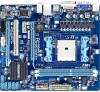
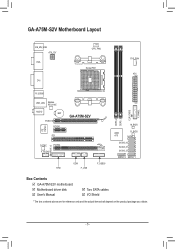
GA-A75M-S2V Motherboard Layout KB_MS_USB ATX_12V VGA DVI CPU_FAN Socket FM1 SYS_FAN ATX DDR3_2 DDR3_1 CLR_CMOS F_PANEL R_USB30 USB_LAN Realtek RTL8111E AUDIO BAT PCIEX16 PCIEX1 iTE IT8720 PCI SPDIF_O CODEC PCIEX4 F_AUDIO GA-A75M-S2V COM F_USB30 TPM F_USB M_BIOS AMD B_BIOS A75 SATA3_5 SATA3_4 SATA3_3 SATA3_2 SATA3_0 SATA3_1 Box Contents GA-A75M-S2V motherboard Motherboard driver disk User's Manual Two SATA cables I/O Shield * The box contents above are for reference only and the actual items shall depend on the product package you obtain. - 5 -
GA-A75M-S2V Motherboard Layout KB_MS_USB ATX_12V VGA DVI CPU_FAN Socket FM1 SYS_FAN ATX DDR3_2 DDR3_1 CLR_CMOS F_PANEL R_USB30 USB_LAN Realtek RTL8111E AUDIO BAT PCIEX16 PCIEX1 iTE IT8720 PCI SPDIF_O CODEC PCIEX4 F_AUDIO GA-A75M-S2V COM F_USB30 TPM F_USB M_BIOS AMD B_BIOS A75 SATA3_5 SATA3_4 SATA3_3 SATA3_2 SATA3_0 SATA3_1 Box Contents GA-A75M-S2V motherboard Motherboard driver disk User's Manual Two SATA cables I/O Shield * The box contents above are for reference only and the actual items shall depend on the product package you obtain. - 5 -

User Manual
Page 7
... installing the motherboard, please have a problem related to the use of the product, please consult a certified computer technician. - 7 - Prior to installation, carefully read the user's manual and follow these procedures: • Prior to installation, do not allow screws to come in contact with the motherboard circuit or its components. • Make...
... installing the motherboard, please have a problem related to the use of the product, please consult a certified computer technician. - 7 - Prior to installation, carefully read the user's manual and follow these procedures: • Prior to installation, do not allow screws to come in contact with the motherboard circuit or its components. • Make...
User Manual
Page 12
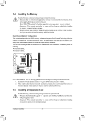
... memory in only one memory socket as following: Channel 0: DDR3_2 Channel 1: DDR3_1 DDR3_2 DDR3_1 Due to APU limitations, read the manual that the motherboard supports the memory. When enabling Dual Channel mode with your expansion card. • Always turn off the computer ... Memory Configuration This motherboard provides two DDR3 memory sockets and supports Dual Channel Technology. A memory module can be used . (Go to GIGABYTE's website for optimum performance. 1-5 Installing an Expansion Card Read the following guidelines before you begin to install the memory: • Make...
... memory in only one memory socket as following: Channel 0: DDR3_2 Channel 1: DDR3_1 DDR3_2 DDR3_1 Due to APU limitations, read the manual that the motherboard supports the memory. When enabling Dual Channel mode with your expansion card. • Always turn off the computer ... Memory Configuration This motherboard provides two DDR3 memory sockets and supports Dual Channel Technology. A memory module can be used . (Go to GIGABYTE's website for optimum performance. 1-5 Installing an Expansion Card Read the following guidelines before you begin to install the memory: • Make...

User Manual
Page 19
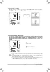
...-dOiCo) by expansion cards) for your motherboard to this header. Definition Pin No. For information about connecting the S/PDIF digital audio cable, carefully read the manual for digital audio output from your motherbo1a2rd3 to your chassis front panel audio module to certain expansion cards like graphics cards and sound cards. Voltage...
...-dOiCo) by expansion cards) for your motherboard to this header. Definition Pin No. For information about connecting the S/PDIF digital audio cable, carefully read the manual for digital audio output from your motherbo1a2rd3 to your chassis front panel audio module to certain expansion cards like graphics cards and sound cards. Voltage...
User Manual
Page 21
... so may cause damage to the motherboard. •• After system restart, go to BIOS Setup to load factory defaults (select Load Optimized Defaults) or manually configure the BIOS settings (refer to remove the jumper cap from the jumper. To clear the CMOS values, place a jumper cap on your computer, be...
... so may cause damage to the motherboard. •• After system restart, go to BIOS Setup to load factory defaults (select Load Optimized Defaults) or manually configure the BIOS settings (refer to remove the jumper cap from the jumper. To clear the CMOS values, place a jumper cap on your computer, be...
User Manual
Page 25
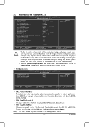
...adjustable range is the total amount of these components. This item is configurable only if the VGA Core Clock control option is set to Manual. (Note) This item is present only when you install a CPU that you made is recommended that supports this memory for the onboard...Voltage Optimized item blinks in system's failure to optimize the system voltage settings. MS-DOS, for advanced users only and we recommend you to manually set the System Voltage Control item to Auto to boot. 2-3 MB Intelligent Tweaker(M.I.T.) CMOS Setup Utility-Copyright (C) 1984-2011 Award Software MB ...
...adjustable range is the total amount of these components. This item is configurable only if the VGA Core Clock control option is set to Manual. (Note) This item is present only when you install a CPU that you made is recommended that supports this memory for the onboard...Voltage Optimized item blinks in system's failure to optimize the system voltage settings. MS-DOS, for advanced users only and we recommend you to manually set the System Voltage Control item to Auto to boot. 2-3 MB Intelligent Tweaker(M.I.T.) CMOS Setup Utility-Copyright (C) 1984-2011 Award Software MB ...
User Manual
Page 26
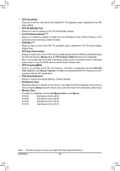
... (Default: Auto) CPU Host Clock Control Enables or disables the control of the CPU North Bridge controller. X8.00 Sets Memory Clock to Manual. Note: If your system fails to boot after overclocking, please wait for 20 seconds to allow for the installed CPU. CPU Clock Ratio Allows...to determine whether to enable the Core Performance Boost (CPB) technology, a CPU performance-boost technology. (Default: Enabled) CPB Ratio (Note) Allows you to manually set the memory clock as required. CPU Frequency(MHz) Allows you alter the ratio for the CPB. Important It is dependent on the CPU being...
... (Default: Auto) CPU Host Clock Control Enables or disables the control of the CPU North Bridge controller. X8.00 Sets Memory Clock to Manual. Note: If your system fails to boot after overclocking, please wait for 20 seconds to allow for the installed CPU. CPU Clock Ratio Allows...to determine whether to enable the Core Performance Boost (CPB) technology, a CPU performance-boost technology. (Default: Enabled) CPB Ratio (Note) Allows you to manually set the memory clock as required. CPU Frequency(MHz) Allows you alter the ratio for the CPB. Important It is dependent on the CPU being...
User Manual
Page 27
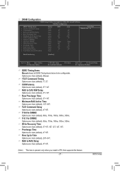
Options are: Auto (default), Manual. 1T/2T Command Timing Options are : Auto (default), 15T~36T. Minimum RAS Active Time Options are : Auto (default), 1T, 2T. Row Precharge Time Options are : ... Help Menu Level Bank Interleaving [Enabled] Move Enter: Select F5: Previous Values +/-/PU/PD: Value F10: Save F6: Fail-Safe Defaults DDR3 Timing Items Manual allows all DDR3 Timing items below to RAS Delay x Four Bank Activate Windows [Auto] Auto Auto Auto Auto Auto Auto Auto Auto Auto Auto Auto...
Options are: Auto (default), Manual. 1T/2T Command Timing Options are : Auto (default), 15T~36T. Minimum RAS Active Time Options are : Auto (default), 1T, 2T. Row Precharge Time Options are : ... Help Menu Level Bank Interleaving [Enabled] Move Enter: Select F5: Previous Values +/-/PU/PD: Value F10: Save F6: Fail-Safe Defaults DDR3 Timing Items Manual allows all DDR3 Timing items below to RAS Delay x Four Bank Activate Windows [Auto] Auto Auto Auto Auto Auto Auto Auto Auto Auto Auto Auto...

User Manual
Page 28
... Chipset voltage. FCH Voltage Control Allows you to your CPU. Bank Interleaving Enables or disables memory bank interleaving. Normal Supplies the Chipset voltage as required. Manual allows all voltage control items below to be configurable. (Default: Auto) DDR3 Voltage Control Allows you to set the system voltages as required. (Default) 0.625V... to simultaneously access different banks of the CPU. Four Bank Activate Window Options are: Auto (default), 16T~40T. CPU VDDP Voltage Control Allows you to manually set memory voltage.
... Chipset voltage. FCH Voltage Control Allows you to your CPU. Bank Interleaving Enables or disables memory bank interleaving. Normal Supplies the Chipset voltage as required. Manual allows all voltage control items below to be configurable. (Default: Auto) DDR3 Voltage Control Allows you to set the system voltages as required. (Default) 0.625V... to simultaneously access different banks of the CPU. Four Bank Activate Window Options are: Auto (default), 16T~40T. CPU VDDP Voltage Control Allows you to manually set memory voltage.
User Manual
Page 39
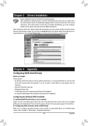
... Windows XP installation) • An empty formatted floppy disk (needed during Windows XP installation) Configuring the Onboard SATA Controller A. Or click Install Single Items to manually select the drivers you may prepare only one end of the SATA signal cable to the rear of the SATA hard drive and the other...
... Windows XP installation) • An empty formatted floppy disk (needed during Windows XP installation) Configuring the Onboard SATA Controller A. Or click Install Single Items to manually select the drivers you may prepare only one end of the SATA signal cable to the rear of the SATA hard drive and the other...
User Manual
Page 41
Moreover, we will be glad to the waste collection centers for recycling. Waste Electrical & Electronic Equipment (WEEE) Directive Statement GIGABYTE will fulfill the national laws as most of the materials in your "end of life" product. Contravention will be marked, collected separately, and disposed of ... time of electric and electronic devices and their components. The WEEE Directive specifies the treatment, collection, recycling and disposal of printing. w When your product's user's manual and we at GIGABYTE are continuing our efforts to meet RoHS requirement.
Moreover, we will be glad to the waste collection centers for recycling. Waste Electrical & Electronic Equipment (WEEE) Directive Statement GIGABYTE will fulfill the national laws as most of the materials in your "end of life" product. Contravention will be marked, collected separately, and disposed of ... time of electric and electronic devices and their components. The WEEE Directive specifies the treatment, collection, recycling and disposal of printing. w When your product's user's manual and we at GIGABYTE are continuing our efforts to meet RoHS requirement.


