User Manual
Page 4
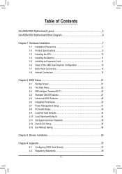
Table of Contents GA-A55M-DS2 Motherboard Layout 5 GA-A55M-DS2 Motherboard Block Diagram 6 Chapter 1 Hardware Installation 7 1-1 Installation Precautions 7 1-2 Product Specifications 8 1-3 Installing the APU 10 1-4 Installing the Memory 11 1-5 Installing an Expansion Card 11 1-6 Setup of the AMD Dual Graphics Configuration 12 1-7 Back Panel Connectors 13 1-8 Internal Connectors 14 Chapter 2 BIOS Setup 21 2-1 ...
Table of Contents GA-A55M-DS2 Motherboard Layout 5 GA-A55M-DS2 Motherboard Block Diagram 6 Chapter 1 Hardware Installation 7 1-1 Installation Precautions 7 1-2 Product Specifications 8 1-3 Installing the APU 10 1-4 Installing the Memory 11 1-5 Installing an Expansion Card 11 1-6 Setup of the AMD Dual Graphics Configuration 12 1-7 Back Panel Connectors 13 1-8 Internal Connectors 14 Chapter 2 BIOS Setup 21 2-1 ...
User Manual
Page 6
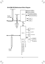
GA-A55M-DS2 Motherboard Block Diagram 1 PCI Express x16 APU CLK+/- (100 MHz) DISP CLK+/- (100 MHz) PCIe CLK (100 MHz) 1 PCI Express x1 AMD APU DDR3 1866/1600/1333/1066 MHz Dual Channel Memory x16 x1 PCI Express Bus x1 DVI-D D-Sub Realtek/Atheros UMI GbE LAN RJ45 LAN 8 USB 2.0/1.1 PCI Bus AMD A55 CODEC Dual BIOS 4 SATA 3Gb/s LPC Bus iTE IT8728 COM Port PS/2 KB/Mouse 1 PCI PCI CLK (33 MHz) MIC (Center/Subwoofer Speaker Out) Line Out (Front Speaker Out) Line In (Rear Speaker Out) S/PDIF Out - 6 -
GA-A55M-DS2 Motherboard Block Diagram 1 PCI Express x16 APU CLK+/- (100 MHz) DISP CLK+/- (100 MHz) PCIe CLK (100 MHz) 1 PCI Express x1 AMD APU DDR3 1866/1600/1333/1066 MHz Dual Channel Memory x16 x1 PCI Express Bus x1 DVI-D D-Sub Realtek/Atheros UMI GbE LAN RJ45 LAN 8 USB 2.0/1.1 PCI Bus AMD A55 CODEC Dual BIOS 4 SATA 3Gb/s LPC Bus iTE IT8728 COM Port PS/2 KB/Mouse 1 PCI PCI CLK (33 MHz) MIC (Center/Subwoofer Speaker Out) Line Out (Front Speaker Out) Line In (Rear Speaker Out) S/PDIF Out - 6 -
User Manual
Page 7
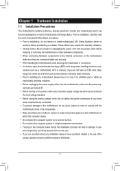
... leads or connectors. •• It is best to the use of the product, please consult a certified computer technician. - 7 - ponents such as a motherboard, APU or memory.
... leads or connectors. •• It is best to the use of the product, please consult a certified computer technician. - 7 - ponents such as a motherboard, APU or memory.
User Manual
Page 8
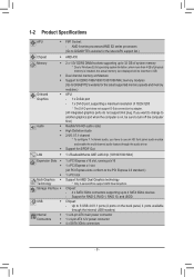
...; 1 x 4-pin ATX 12V power connector ŠŠ 4 x SATA 3Gb/s connectors - 8 - AMD A series processors/AMD E2 series processors (Go to GIGABYTE's website for the latest APU support list.) Chipset ŠŠ AMD A55 Memory Onboard Graphics Audio ŠŠ 2 x 1.5V DDR3 DIMM sockets supporting up to another graphics port when the computer is...
...; 1 x 4-pin ATX 12V power connector ŠŠ 4 x SATA 3Gb/s connectors - 8 - AMD A series processors/AMD E2 series processors (Go to GIGABYTE's website for the latest APU support list.) Chipset ŠŠ AMD A55 Memory Onboard Graphics Audio ŠŠ 2 x 1.5V DDR3 DIMM sockets supporting up to another graphics port when the computer is...
User Manual
Page 10
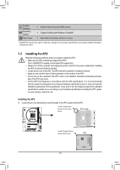
... accordance with the APU specifications. If you begin to install the APU: • Make sure that the motherboard supports the APU. (Go to GIGABYTE's website for the peripherals. age of the Socket FM1 Socket A Small Triangle Marking Denotes APU Pin One APU - 10 - The APU cannot ...before you wish to set the frequency beyond the standard specifications, please do so according to your hardware specifications including the APU, graphics card, memory, hard drive, etc. Locate the pin one of the APU. Installing the APU A. It is not installed, otherwise overheating and dam- ...
... accordance with the APU specifications. If you begin to install the APU: • Make sure that the motherboard supports the APU. (Go to GIGABYTE's website for the peripherals. age of the Socket FM1 Socket A Small Triangle Marking Denotes APU Pin One APU - 10 - The APU cannot ...before you wish to set the frequency beyond the standard specifications, please do so according to your hardware specifications including the APU, graphics card, memory, hard drive, etc. Locate the pin one of the APU. Installing the APU A. It is not installed, otherwise overheating and dam- ...
User Manual
Page 11
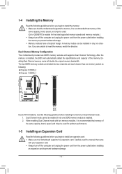
...direction. Enabling Dual Channel memory mode will automatically detect the specifications and capacity of the same capacity, brand, speed, and chips be installed in Dual Channel mode. 111 Dual Channel mode cannot be used . (Go to GIGABYTE's website for optimum performance.... 1-5 Installing an Expansion Card Read the following guidelines before you begin to install the memory: •• Make sure that the motherboard supports the memory. After the memory is installed, the BIOS will double the original memory bandwidth. A memory ...
...direction. Enabling Dual Channel memory mode will automatically detect the specifications and capacity of the same capacity, brand, speed, and chips be installed in Dual Channel mode. 111 Dual Channel mode cannot be used . (Go to GIGABYTE's website for optimum performance.... 1-5 Installing an Expansion Card Read the following guidelines before you begin to install the memory: •• Make sure that the motherboard supports the memory. After the memory is installed, the BIOS will double the original memory bandwidth. A memory ...
User Manual
Page 23
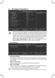
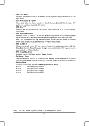
... CPU Clock Ratio Core Performance Boost (Note) CPB Ratio (Note) CPU Host Clock Control x CPU Host Clock PCIe Spread Spectrum Set Memory Clock x Memory Clock } DRAM Configuration ******** System Voltage Optimized ******** System Voltage Control x DDR3 Voltage Control x FCH Voltage Control x APU VDDP Voltage Control...When the System Voltage Optimized item blinks in red, it is recommended that supports this feature. - 23 - If this memory for example, will work stably with the overclock/overvoltage settings you install a CPU that you not to alter the default ...
... CPU Clock Ratio Core Performance Boost (Note) CPB Ratio (Note) CPU Host Clock Control x CPU Host Clock PCIe Spread Spectrum Set Memory Clock x Memory Clock } DRAM Configuration ******** System Voltage Optimized ******** System Voltage Control x DDR3 Voltage Control x FCH Voltage Control x APU VDDP Voltage Control...When the System Voltage Optimized item blinks in red, it is recommended that supports this feature. - 23 - If this memory for example, will work stably with the overclock/overvoltage settings you install a CPU that you not to alter the default ...
User Manual
Page 24
.... (Default: Enabled) CPB Ratio (Note) Allows you install a CPU that the CPU frequency be configurable. X5.33 Sets Memory Clock to X6.66. X6.66 Sets Memory Clock to X5.33. Core Performance Boost (Note) Allows you to determine whether to Manual. Auto (default) allows the BIOS... option is configurable only when CPU Host Clock Control is highly recommended that supports this feature. - 24 - Important It is set the memory clock as required. The adjustable range is present only when you alter the ratio for automated system reboot, or clear the CMOS values to...
.... (Default: Enabled) CPB Ratio (Note) Allows you install a CPU that the CPU frequency be configurable. X5.33 Sets Memory Clock to X6.66. X6.66 Sets Memory Clock to X5.33. Core Performance Boost (Note) Allows you to determine whether to Manual. Auto (default) allows the BIOS... option is configurable only when CPU Host Clock Control is highly recommended that supports this feature. - 24 - Important It is set the memory clock as required. The adjustable range is present only when you alter the ratio for automated system reboot, or clear the CMOS values to...
User Manual
Page 26
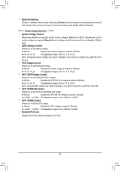
.... (Default: Auto) DDR3 Voltage Control Allows you to +0.300V. Note: Increasing memory voltage may result in damage to the memory or reduce the useful life of the memory to increase memory performance and stability. (Default: Enabled) ******** System Voltage Optimized System Voltage Control Determines.... Note: Increasing APU voltage may result in damage to set the CPU NorthBridge VID voltage. Bank Interleaving Enables or disables memory bank interleaving. APU VDDP Voltage Control Allows you to +0.400V. Normal Supplies the CPU voltage as required. (Default) +0....
.... (Default: Auto) DDR3 Voltage Control Allows you to +0.300V. Note: Increasing memory voltage may result in damage to the memory or reduce the useful life of the memory to increase memory performance and stability. (Default: Enabled) ******** System Voltage Optimized System Voltage Control Determines.... Note: Increasing APU voltage may result in damage to set the CPU NorthBridge VID voltage. Bank Interleaving Enables or disables memory bank interleaving. APU VDDP Voltage Control Allows you to +0.400V. Normal Supplies the CPU voltage as required. (Default) +0....
User Manual
Page 27
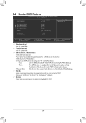
...0 Master } IDE Channel 0 Slave } IDE Channel 1 Master } IDE Channel 1 Slave [None] [None] [None] [None] Halt On [All, But Keyboard] Base Memory Extended Memory 640K 941M Move Enter: Select F5: Previous Values +/-/PU/PD: Value F10: Save F6: Fail-Safe Defaults ESC: Exit F1: General Help F7: Optimized Defaults...• None If no SATA devices are used, set this channel. Options are: "All Errors," "No Errors," "All, But Keyboard". (Default) Memory These fields are read-only and are : Auto (default), CHS, LBA, Large. Halt On Allows you to None so the system will stop for...
...0 Master } IDE Channel 0 Slave } IDE Channel 1 Master } IDE Channel 1 Slave [None] [None] [None] [None] Halt On [All, But Keyboard] Base Memory Extended Memory 640K 941M Move Enter: Select F5: Previous Values +/-/PU/PD: Value F10: Save F6: Fail-Safe Defaults ESC: Exit F1: General Help F7: Optimized Defaults...• None If no SATA devices are used, set this channel. Options are: "All Errors," "No Errors," "All, But Keyboard". (Default) Memory These fields are read-only and are : Auto (default), CHS, LBA, Large. Halt On Allows you to None so the system will stop for...

User Manual
Page 32
... is set a password with 1~5 characters to accept. Disabled Disables this item and set to Password. To turn on upon the return of the AC power. Memory The system returns to turn on this function, you need an ATX power supply providing at a specific time on each day or on by a wake...
... is set a password with 1~5 characters to accept. Disabled Disables this item and set to Password. To turn on upon the return of the AC power. Memory The system returns to turn on this function, you need an ATX power supply providing at a specific time on each day or on by a wake...
User Manual
Page 37
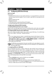
... key to Y. Press the key or to change the Assignment option to select RAID 0. 2. Make sure OnChip SATA Controller is the default. 3. After the POST memory test begins and before the operating system boot begins, look for your computer and press to RAID. To create a new array, press to the disk...
... key to Y. Press the key or to change the Assignment option to select RAID 0. 2. Make sure OnChip SATA Controller is the default. 3. After the POST memory test begins and before the operating system boot begins, look for your computer and press to RAID. To create a new array, press to the disk...


