User Manual
Page 1
GA-A55-DS3P User's Manual Rev. 1001 12ME-A55DS3P-1001R
GA-A55-DS3P User's Manual Rev. 1001 12ME-A55DS3P-1001R
User Manual
Page 3
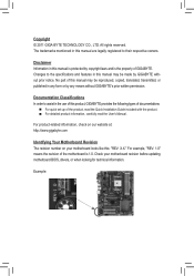
...example, "REV: 1.0" means the revision of the motherboard is the property of GIGABYTE. Copyright © 2011 GIGA-BYTE TECHNOLOGY CO., LTD. Example: Check your motherboard looks like this manual are legally registered to assist in any means without prior notice. Changes to the... specifications and features in this product, GIGABYTE provides the following types of documentations: For quick set-up of this manual may be made by any form or by GIGABYTE without GIGABYTE's prior written permission. No part of this manual may be reproduced, copied, translated, ...
...example, "REV: 1.0" means the revision of the motherboard is the property of GIGABYTE. Copyright © 2011 GIGA-BYTE TECHNOLOGY CO., LTD. Example: Check your motherboard looks like this manual are legally registered to assist in any means without prior notice. Changes to the... specifications and features in this product, GIGABYTE provides the following types of documentations: For quick set-up of this manual may be made by any form or by GIGABYTE without GIGABYTE's prior written permission. No part of this manual may be reproduced, copied, translated, ...
User Manual
Page 5
Chapter 3 Drivers Installation 55 3-1 Installing Chipset Drivers 55 3-2 Application Software 56 3-3 Technical Manuals 56 3-4 Contact...57 3-5 System...57 3-6 Download Center 58 3-7 New Utilities...58 Chapter 4 Unique Features 59 4-1 Xpress Recovery2 59 4-2 BIOS Update Utilities 62 4-2-1 Updating the BIOS ...
Chapter 3 Drivers Installation 55 3-1 Installing Chipset Drivers 55 3-2 Application Software 56 3-3 Technical Manuals 56 3-4 Contact...57 3-5 System...57 3-6 Download Center 58 3-7 New Utilities...58 Chapter 4 Unique Features 59 4-1 Xpress Recovery2 59 4-2 BIOS Update Utilities 62 4-2-1 Updating the BIOS ...

User Manual
Page 6
The box contents are for reference only and the actual items shall depend on the product package you obtain. Optional Items 2-port USB 2.0 bracket (Part No. 12CR1-1UB030-5*R) 2-port SATA power cable (Part No. 12CF1-2SERPW-0*R) COM port cable (Part No. 12CF1-1CM001-3*R) - 6 - Box Contents GA-A55-DS3P motherboard Motherboard driver disk User's Manual Quick Installation Guide Four SATA cables I/O Shield The box contents above are subject to change without notice.
The box contents are for reference only and the actual items shall depend on the product package you obtain. Optional Items 2-port USB 2.0 bracket (Part No. 12CR1-1UB030-5*R) 2-port SATA power cable (Part No. 12CF1-2SERPW-0*R) COM port cable (Part No. 12CF1-1CM001-3*R) - 6 - Box Contents GA-A55-DS3P motherboard Motherboard driver disk User's Manual Quick Installation Guide Four SATA cables I/O Shield The box contents above are subject to change without notice.
User Manual
Page 9
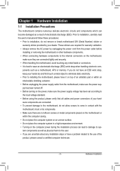
... power during the installation process can become damaged as a result of the product, please consult a certified computer technician. - 9 - Prior to installation, carefully read the user's manual and follow these procedures: •• Prior to wear an electrostatic discharge (ESD) wrist strap when handling electronic com-
... power during the installation process can become damaged as a result of the product, please consult a certified computer technician. - 9 - Prior to installation, carefully read the user's manual and follow these procedures: •• Prior to wear an electrostatic discharge (ESD) wrist strap when handling electronic com-
User Manual
Page 15
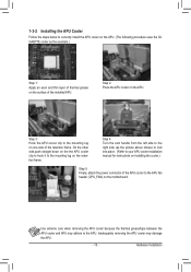
... the steps below to correctly install the APU cooler on the APU. (The following procedure uses the GIGABYTE cooler as the picture above shows) to lock into place. (Refer to your APU cooler installation manual for instructions on installing the cooler.) Step 5: Finally, attach the power connector of the APU cooler to...
... the steps below to correctly install the APU cooler on the APU. (The following procedure uses the GIGABYTE cooler as the picture above shows) to lock into place. (Refer to your APU cooler installation manual for instructions on installing the cooler.) Step 5: Finally, attach the power connector of the APU cooler to...
User Manual
Page 18
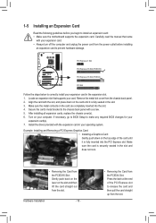
1-5 Installing an Expansion Card Read the following guidelines before installing an expansion card to prevent hardware damage. Carefully read the manual that supports your card. Turn on the slot and then lift the card straight out from the PCIEX4 Slot: Press the latch at the end ...
1-5 Installing an Expansion Card Read the following guidelines before installing an expansion card to prevent hardware damage. Carefully read the manual that supports your card. Turn on the slot and then lift the card straight out from the PCIEX4 Slot: Press the latch at the end ...
User Manual
Page 24
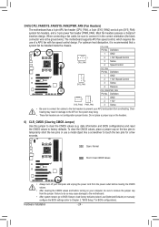
... system may cause damage to the motherboard. •• After system restart, go to BIOS Setup to load factory defaults (select Load Optimized Defaults) or manually configure the BIOS settings (refer to do so may hang. •• These fan headers are not configuration jumper blocks. Hardware Installation - 24 - CPU_FAN: Pin...
... system may cause damage to the motherboard. •• After system restart, go to BIOS Setup to load factory defaults (select Load Optimized Defaults) or manually configure the BIOS settings (refer to do so may hang. •• These fan headers are not configuration jumper blocks. Hardware Installation - 24 - CPU_FAN: Pin...
User Manual
Page 27
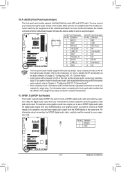
... the motherboard header will be present on each wire instead of a single plug. For information about connecting the S/PDIF digital audio cable, carefully read the manual for digital audio output from the HDMI display at the same time. Pin No. 10) F_AUDIO (Front Panel Audio Header) The front panel audio header...
... the motherboard header will be present on each wire instead of a single plug. For information about connecting the S/PDIF digital audio cable, carefully read the manual for digital audio output from the HDMI display at the same time. Pin No. 10) F_AUDIO (Front Panel Audio Header) The front panel audio header...
User Manual
Page 36
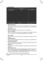
...is configurable only when the VGA Core Clock control option is set to be configurable. Manual allows the CPU Frequency (MHz) item below to Manual. VGA Core Clock control Allows you to determine whether to manually set the VGA Core clock. The adjustable range is dependent on the CPU being ...is present only when you to determine whether to alter the North Bridge controller frequency for display. The adjustable range is from 300 MHz to manually set the VGA Core clock. (Default: Auto) VGA Core Clock(MHz) Allows you to 2000 MHz. CPU NorthBridge Freq. Core Performance Boost...
...is configurable only when the VGA Core Clock control option is set to be configurable. Manual allows the CPU Frequency (MHz) item below to Manual. VGA Core Clock control Allows you to determine whether to manually set the VGA Core clock. The adjustable range is dependent on the CPU being ...is present only when you to determine whether to alter the North Bridge controller frequency for display. The adjustable range is from 300 MHz to manually set the VGA Core clock. (Default: Auto) VGA Core Clock(MHz) Allows you to 2000 MHz. CPU NorthBridge Freq. Core Performance Boost...
User Manual
Page 37
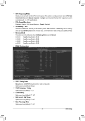
... the CPU host frequency. Row Precharge Time Options are : Auto (default), 5T~14T. CPU Frequency(MHz) Allows you to manually set the memory clock as required. This option is configurable only when CPU Host Clock Control is set in accordance with the ...CPU specifications. PCIe Spread Spectrum Enables or disables PCIe Spread Spectrum. (Default: Disabled) Set Memory Clock Determines whether to manually set to Manual. DRAM Configuration CMOS Setup Utility-Copyright (C) 1984-2011 Award Software DRAM Configuration DDR3 Timing Items Auto] SPD Auto x 1T/2T ...
... the CPU host frequency. Row Precharge Time Options are : Auto (default), 5T~14T. CPU Frequency(MHz) Allows you to manually set the memory clock as required. This option is configurable only when CPU Host Clock Control is set in accordance with the ...CPU specifications. PCIe Spread Spectrum Enables or disables PCIe Spread Spectrum. (Default: Disabled) Set Memory Clock Determines whether to manually set to Manual. DRAM Configuration CMOS Setup Utility-Copyright (C) 1984-2011 Award Software DRAM Configuration DDR3 Timing Items Auto] SPD Auto x 1T/2T ...
User Manual
Page 38
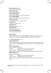
...), 20T~54T. Auto lets the BIOS automatically set the system voltages. TwTr Command Delay Options are : Auto (default), 15T~36T. RAS to manually set the system voltages as required. (Default) 2.100V ~ 2.900V The adjustable range is from 2.100V to the memory or reduce the useful life... (default), 4T~8T. Trfc0 for DIMM2, DIMM4 Options are : Auto (default), 16T~40T. Normal Supplies the CPU PLL voltage as required. Manual allows all voltage control items below to be configurable. (Default: Auto) CPU PLL Voltage Control Allows you to set the CPU PLL voltage. DDR3...
...), 20T~54T. Auto lets the BIOS automatically set the system voltages. TwTr Command Delay Options are : Auto (default), 15T~36T. RAS to manually set the system voltages as required. (Default) 2.100V ~ 2.900V The adjustable range is from 2.100V to the memory or reduce the useful life... (default), 4T~8T. Trfc0 for DIMM2, DIMM4 Options are : Auto (default), 16T~40T. Normal Supplies the CPU PLL voltage as required. Manual allows all voltage control items below to be configurable. (Default: Auto) CPU PLL Voltage Control Allows you to set the CPU PLL voltage. DDR3...
User Manual
Page 55
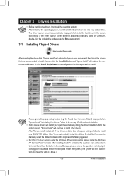
...click No if you wish to do so may affect the driver installation. •• Some device drivers will continue to install new GIGABYTE utilities. Drivers Installation Failure to install. •• Please ignore the popup dialog box(es) (e.g. After the system restart, "... insert the motherboard driver disk into your system automatically during the driver installation. Or click Install Single Items to manually select the drivers you want to manually select the utilities to install. The driver Autorun screen is installing the drivers. After installing the SP1 (or...
...click No if you wish to do so may affect the driver installation. •• Some device drivers will continue to install new GIGABYTE utilities. Drivers Installation Failure to install. •• Please ignore the popup dialog box(es) (e.g. After the system restart, "... insert the motherboard driver disk into your system automatically during the driver installation. Or click Install Single Items to manually select the drivers you want to manually select the utilities to install. The driver Autorun screen is installing the drivers. After installing the SP1 (or...
User Manual
Page 56
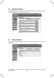
3-2 Application Software This page displays all the utilities and applications that GIGABYTE develops and some free software. Drivers Installation - 56 - You can click the Install button on the right of an item to install it. 3-3 Technical Manuals This page provides GIGABYTE's application guides, content descriptions for this driver disk, and the motherboard manuals.
3-2 Application Software This page displays all the utilities and applications that GIGABYTE develops and some free software. Drivers Installation - 56 - You can click the Install button on the right of an item to install it. 3-3 Technical Manuals This page provides GIGABYTE's application guides, content descriptions for this driver disk, and the motherboard manuals.
User Manual
Page 62
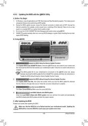
...latest BIOS file from the hassles of system safety, users cannot update the backup BIOS manually. However, if the BIOS update file is Q-Flash™? Inadequate BIOS flashing may ... Embedded in system malfunction. During the POST, press the key to your motherboard model. 2. From GIGABYTE's website, download the latest compressed BIOS update file that support DualBIOS have two BIOS onboard, a ...file and save the new BIOS file (e.g. A55DS3P.F1) to enter Q-Flash. Restart the system. GA-A55-DS3P F1a . . . . : BIOS Setup : XpressRecovery2 : Boot Menu : Qflash 06/18/2011-Llano-Hudson-...
...latest BIOS file from the hassles of system safety, users cannot update the backup BIOS manually. However, if the BIOS update file is Q-Flash™? Inadequate BIOS flashing may ... Embedded in system malfunction. During the POST, press the key to your motherboard model. 2. From GIGABYTE's website, download the latest compressed BIOS update file that support DualBIOS have two BIOS onboard, a ...file and save the new BIOS file (e.g. A55DS3P.F1) to enter Q-Flash. Restart the system. GA-A55-DS3P F1a . . . . : BIOS Setup : XpressRecovery2 : Boot Menu : Qflash 06/18/2011-Llano-Hudson-...
User Manual
Page 65
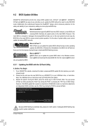
... TSR (Terminate and Stay Resident) programs. This helps prevent unexpected failures when performing a BIOS update. 2. Do not use the G.O.M. (GIGABYTE Online Management) function when using @BIOS. 4. After Updating the BIOS Restart your motherboard model. Follow the on -screen instructions to your ...the BIOS with an incorrect BIOS file could cause your motherboard is not present on the @BIOS server site, please manually download the BIOS update file from GIGABYTE Server, select the @BIOS server site closest to complete. 3. Follow the on -screen instructions to boot. - 65...
... TSR (Terminate and Stay Resident) programs. This helps prevent unexpected failures when performing a BIOS update. 2. Do not use the G.O.M. (GIGABYTE Online Management) function when using @BIOS. 4. After Updating the BIOS Restart your motherboard model. Follow the on -screen instructions to your ...the BIOS with an incorrect BIOS file could cause your motherboard is not present on the @BIOS server site, please manually download the BIOS update file from GIGABYTE Server, select the @BIOS server site closest to complete. 3. Follow the on -screen instructions to boot. - 65...
User Manual
Page 74
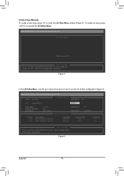
... Utility (c) 2011 Advanced Micro Devices, Inc. LD No LD Name LD 1 Logical Drive 1 [ LD Define Menu ] RAID Mode Drv RAID 0 0 Stripe Block Gigabyte Boundary Read Policy 64 KB ON Read Ahead Initialization ON Write Policy WriteBack [ Drives Assignments ] Port:ID 01:00 02:00 Drive Model WDC WD800JD...80.02 Assignment N N [[KKeeyyssAAvvaailialabblele]] [h] Up [i] Down [PaUp/PaDn] Switch Page [Space] Change Option [Ctrl+Y] Save [ESC] Exit Figure 5 Appendix - 74 - Create Arrays Manually To create a new array, press to enter the LD View Menu window (Figure 4).
... Utility (c) 2011 Advanced Micro Devices, Inc. LD No LD Name LD 1 Logical Drive 1 [ LD Define Menu ] RAID Mode Drv RAID 0 0 Stripe Block Gigabyte Boundary Read Policy 64 KB ON Read Ahead Initialization ON Write Policy WriteBack [ Drives Assignments ] Port:ID 01:00 02:00 Drive Model WDC WD800JD...80.02 Assignment N N [[KKeeyyssAAvvaailialabblele]] [h] Up [i] Down [PaUp/PaDn] Switch Page [Space] Change Option [Ctrl+Y] Save [ESC] Exit Figure 5 Appendix - 74 - Create Arrays Manually To create a new array, press to enter the LD View Menu window (Figure 4).
User Manual
Page 81
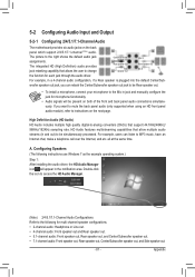
... each jack through the audio driver. HD Audio features multistreaming capabilities that allow multiple audio streams (in and out) to the Mic in jack and manually configure the jack for microphone functionality. • Audio signals will appear in a 4-channel audio configuration, if a Rear speaker is plugged into the default Center/Sub...
... each jack through the audio driver. HD Audio features multistreaming capabilities that allow multiple audio streams (in and out) to the Mic in jack and manually configure the jack for microphone functionality. • Audio signals will appear in a 4-channel audio configuration, if a Rear speaker is plugged into the default Center/Sub...


