Manual
Page 4
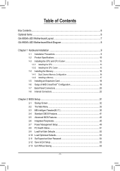
...GA-990XA-UD3 Motherboard Layout 7 GA-990XA-UD3 Motherboard Block Diagram 8 Chapter 1 Hardware Installation 9 1-1 Installation Precautions 9 1-2 Product Specifications 10 1-3 Installing the CPU and CPU Cooler 13 1-3-1 Installing the CPU 13 1-3-2 Installing the CPU Cooler 15 1-4 Installing the Memory 16 1-4-1 Dual Channel Memory Configuration... 16 1-4-2 Installing a Memory 17 1-5 Installing an Expansion Card 18 1-6 Setup of AMD CrossFireX™ Configuration 19 1-7 Back Panel Connectors 20 1-8 Internal Connectors 22 Chapter 2 BIOS Setup 31 2-1 ...
...GA-990XA-UD3 Motherboard Layout 7 GA-990XA-UD3 Motherboard Block Diagram 8 Chapter 1 Hardware Installation 9 1-1 Installation Precautions 9 1-2 Product Specifications 10 1-3 Installing the CPU and CPU Cooler 13 1-3-1 Installing the CPU 13 1-3-2 Installing the CPU Cooler 15 1-4 Installing the Memory 16 1-4-1 Dual Channel Memory Configuration... 16 1-4-2 Installing a Memory 17 1-5 Installing an Expansion Card 18 1-6 Setup of AMD CrossFireX™ Configuration 19 1-7 Back Panel Connectors 20 1-8 Internal Connectors 22 Chapter 2 BIOS Setup 31 2-1 ...

Manual
Page 5
... Utilities 64 4-2-1 Updating the BIOS with the Q-Flash Utility 64 4-2-2 Updating the BIOS with the @BIOS Utility 67 4-3 EasyTune 6...68 4-4 Easy Energy Saver 69 4-5 Q-Share...71 4-6 SMART Recovery 72 4-7 Auto Green...73 4-8 Cloud OC...74 Chapter 5 Appendix...75 5-1 Configuring SATA Hard Drive(s 75 5-1-1 Configuring SATA Controllers 75 5-1-2 Installing the SATA RAID/AHCI Driver and Operating...
... Utilities 64 4-2-1 Updating the BIOS with the Q-Flash Utility 64 4-2-2 Updating the BIOS with the @BIOS Utility 67 4-3 EasyTune 6...68 4-4 Easy Energy Saver 69 4-5 Q-Share...71 4-6 SMART Recovery 72 4-7 Auto Green...73 4-8 Cloud OC...74 Chapter 5 Appendix...75 5-1 Configuring SATA Hard Drive(s 75 5-1-1 Configuring SATA Controllers 75 5-1-2 Installing the SATA RAID/AHCI Driver and Operating...
Manual
Page 16
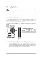
...the same capacity, brand, speed, and chips be used . (Go to GIGABYTE's website for optimum performance. when enabling Dual Channel mode with two or four memory modules, it is installed, the BIOS will double the original memory bandwidth. A memory module can be used and...into two channels and each channel has two memory sockets as following: Channel 0: DDR3_2, DDR3_4 Channel 1: DDR3_1, DDR3_3 Dual Channel Memory Configurations Table Two Modules Four Modules DDR3_4 - 1-4 Installing the Memory Read the following guidelines before installing the memory to prevent hardware damage. ...
...the same capacity, brand, speed, and chips be used . (Go to GIGABYTE's website for optimum performance. when enabling Dual Channel mode with two or four memory modules, it is installed, the BIOS will double the original memory bandwidth. A memory module can be used and...into two channels and each channel has two memory sockets as following: Channel 0: DDR3_2, DDR3_4 Channel 1: DDR3_1, DDR3_3 Dual Channel Memory Configurations Table Two Modules Four Modules DDR3_4 - 1-4 Installing the Memory Read the following guidelines before installing the memory to prevent hardware damage. ...

Manual
Page 25
... more information). • SPEAK (Speaker, Orange): Connects to indicate the problem. When connecting your system using the power switch (refer to Chapter 2, "BIOS Setup," "Power Management Setup," for information about beep codes. • HD (Hard Drive Activity LED, Blue) Connects to the hard drive activity LED ... the chassis cover has been removed. If a problem is in S1 sleep state. RESRES+ CICI+ PWR+ PWR- The front panel design may configure the way to turn off (S5). • PW (Power Switch, Red): Connects to the power status indicator on the chassis front panel....
... more information). • SPEAK (Speaker, Orange): Connects to indicate the problem. When connecting your system using the power switch (refer to Chapter 2, "BIOS Setup," "Power Management Setup," for information about beep codes. • HD (Hard Drive Activity LED, Blue) Connects to the hard drive activity LED ... the chassis cover has been removed. If a problem is in S1 sleep state. RESRES+ CICI+ PWR+ PWR- The front panel design may configure the way to turn off (S5). • PW (Power Switch, Red): Connects to the power status indicator on the chassis front panel....

Manual
Page 29
... SB3V 16 SERIRQ 17 GND 18 NC 19 NC 20 SUSCLK 15) BAT (Battery) The battery provides power to keep the values (such as BIOS configurations, date, and time information) in the CMOS when the computer is replaced with an incorrect model. •• Contact the place of the... a metal object like a screwdriver to this header. Danger of the battery (the positive side should face up). •• Used batteries must be lost. DB_PORT BIOS Switc 1 1 19 TPM w/housing 20 Pin No. 1 2 3 4 5 6 7 8 9 10 Definition LCLK GND LFRAME No Pin LRESET NC LAD3 LAD2 VCC3 LAD1 1 Voltage ...
... SB3V 16 SERIRQ 17 GND 18 NC 19 NC 20 SUSCLK 15) BAT (Battery) The battery provides power to keep the values (such as BIOS configurations, date, and time information) in the CMOS when the computer is replaced with an incorrect model. •• Contact the place of the... a metal object like a screwdriver to this header. Danger of the battery (the positive side should face up). •• Used batteries must be lost. DB_PORT BIOS Switc 1 1 19 TPM w/housing 20 Pin No. 1 2 3 4 5 6 7 8 9 10 Definition LCLK GND LFRAME No Pin LRESET NC LAD3 LAD2 VCC3 LAD1 1 Voltage ...
Manual
Page 30
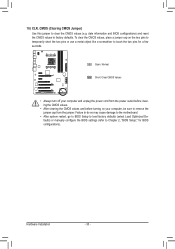
... (e.g. Failure to do so may cause damage to the motherboard. •• After system restart, go to BIOS Setup to load factory defaults (select Load Optimized Defaults) or manually configure the BIOS settings (refer to Chapter 2, "BIOS Setup," for a few seconds. To clear the CMOS values, place a jumper cap on your computer and unplug... defaults. Hardware Installation - 30 - Open: Normal Short: Clear CMOS Values •• Always turn off your computer, be sure to touch the two pins for BIOS configurations).
... (e.g. Failure to do so may cause damage to the motherboard. •• After system restart, go to BIOS Setup to load factory defaults (select Load Optimized Defaults) or manually configure the BIOS settings (refer to Chapter 2, "BIOS Setup," for a few seconds. To clear the CMOS values, place a jumper cap on your computer and unplug... defaults. Hardware Installation - 30 - Open: Normal Short: Clear CMOS Values •• Always turn off your computer, be sure to touch the two pins for BIOS configurations).

Manual
Page 31
... (unless you do it is recommended that searches and downloads the latest version of BIOS from the Internet and updates the BIOS. To upgrade the BIOS, use either the GIGABYTE Q-Flash or @BIOS utility. • Q-Flash allows the user to quickly and easily upgrade or back... user to modify basic system configuration settings or to boot. Inadequate BIOS flashing may result in system's failure to activate certain system features. For instructions on . Chapter 2 BIOS Setup BIOS (Basic Input and Output System) records hardware parameters of the BIOS Setup program. Its major functions...
... (unless you do it is recommended that searches and downloads the latest version of BIOS from the Internet and updates the BIOS. To upgrade the BIOS, use either the GIGABYTE Q-Flash or @BIOS utility. • Q-Flash allows the user to quickly and easily upgrade or back... user to modify basic system configuration settings or to boot. Inadequate BIOS flashing may result in system's failure to activate certain system features. For instructions on . Chapter 2 BIOS Setup BIOS (Basic Input and Output System) records hardware parameters of the BIOS Setup program. Its major functions...

Manual
Page 32
... Screen Motherboard Model BIOS Version Award Modular BIOS v6.00PG Copyright (C) 1984-2011, Award Software, Inc. GA-990XA-UD3 F1a . . . . : BIOS Setup : XpressRecovery2 : Boot Menu : Qflash 04/22/2011-RD990-SB950-7A66FG02C-00 Function Keys Function Keys: : POST SCREEN Press the key to show the BIOS POST screen at ...: Q-FLASH Press the key to Xpress Recovery2 during the POST. BIOS Setup - 32 - To show the BIOS POST screen. After system restart, the device boot order will directly boot from the device configured in Boot Menu is effective for subsequent access to access the Q-Flash...
... Screen Motherboard Model BIOS Version Award Modular BIOS v6.00PG Copyright (C) 1984-2011, Award Software, Inc. GA-990XA-UD3 F1a . . . . : BIOS Setup : XpressRecovery2 : Boot Menu : Qflash 04/22/2011-RD990-SB950-7A66FG02C-00 Function Keys Function Keys: : POST SCREEN Press the key to show the BIOS POST screen at ...: Q-FLASH Press the key to Xpress Recovery2 during the POST. BIOS Setup - 32 - To show the BIOS POST screen. After system restart, the device boot order will directly boot from the device configured in Boot Menu is effective for subsequent access to access the Q-Flash...

Manual
Page 34
...to erase the default profile name, use this function to load the BIOS settings from BIOS If your CPU, memory, etc. Standard CMOS Features Use this menu to configure all changes and the previous settings remain in BIOS Setup. Set User Password Change, set , or disable ... Load CMOS from a profile created before, without the hassles of errors that stop the system boot, etc. Advanced BIOS Features Use this menu to configure the device boot order, advanced features available on the CPU, and the primary display adapter. Integrated Peripherals Use this ...
...to erase the default profile name, use this function to load the BIOS settings from BIOS If your CPU, memory, etc. Standard CMOS Features Use this menu to configure all changes and the previous settings remain in BIOS Setup. Set User Password Change, set , or disable ... Load CMOS from a profile created before, without the hassles of errors that stop the system boot, etc. Advanced BIOS Features Use this menu to configure the device boot order, advanced features available on the CPU, and the primary display adapter. Integrated Peripherals Use this ...
Manual
Page 35
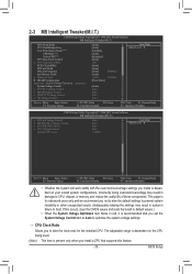
...the settings may result in system's failure to CPU, chipset, or memory and reduce the useful life of these components. BIOS Setup Core Performance Boost (Note) CPB Ratio (Note) Turbo CPB (Note) CPU Host Clock Control x CPU Frequency(MHz...) PCIE Clock(MHz) HT Link Width HT Link Frequency Set Memory Clock x Memory Clock } DRAM Configuration ******** System Voltage Optimized ******** System Voltage Control x CPU PLL Voltage Control x DRAM Voltage Control x DDR VTT Voltage Control x NB Voltage Control...
...the settings may result in system's failure to CPU, chipset, or memory and reduce the useful life of these components. BIOS Setup Core Performance Boost (Note) CPB Ratio (Note) Turbo CPB (Note) CPU Host Clock Control x CPU Frequency(MHz...) PCIE Clock(MHz) HT Link Width HT Link Frequency Set Memory Clock x Memory Clock } DRAM Configuration ******** System Voltage Optimized ******** System Voltage Control x CPU PLL Voltage Control x DRAM Voltage Control x DDR VTT Voltage Control x NB Voltage Control...
Manual
Page 36
...MHz) item below to be set the CPU host frequency. The adjustable range is set to manually set the memory clock. This option is configurable only when CPU Host Clock Control is from 100 MHz to Manual. HT Link Frequency Allows you to Manual. Set Memory Clock Determines whether ... X5.33 Sets Memory Clock to manually set the frequency for the installed CPU. The adjustable range is from 200 MHz to be configurable. Auto (default) allows the BIOS to improve CPU performance. (Default: Disabled) CPU Host Clock Control Enables or disables the control of CPU host clock. PCIE Clock(...
...MHz) item below to be set the CPU host frequency. The adjustable range is set to manually set the memory clock. This option is configurable only when CPU Host Clock Control is from 100 MHz to Manual. HT Link Frequency Allows you to Manual. Set Memory Clock Determines whether ... X5.33 Sets Memory Clock to manually set the frequency for the installed CPU. The adjustable range is from 200 MHz to be configurable. Auto (default) allows the BIOS to improve CPU performance. (Default: Disabled) CPU Host Clock Control Enables or disables the control of CPU host clock. PCIE Clock(...

Manual
Page 37
... Timing items below to RAS Delay **DCTs Drive Strength** [Auto] 200 [Auto] x6.66 1333Mhz [Unganged] [Auto] SPD Auto Auto -- -- BIOS Setup Auto 9T 9T Auto 9T 9T Auto 9T 9T Auto 24T 24T Auto 5T 5T Auto 110ns 110ns Auto -- -- Auto 10T 10T Auto 5T... Save F6: Fail-Safe Defaults ESC: Exit F1: General Help F7: Optimized Defaults CMOS Setup Utility-Copyright (C) 1984-2011 Award Software DRAM Configuration ProcOdt(ohms) DQS Drive Strength Data Drive Strength MEMCLK Drive Strength Addr/Cmd Drive Strength CS/ODT Drive Strength CKE Drive Strength **DCTs Addr...
... Timing items below to RAS Delay **DCTs Drive Strength** [Auto] 200 [Auto] x6.66 1333Mhz [Unganged] [Auto] SPD Auto Auto -- -- BIOS Setup Auto 9T 9T Auto 9T 9T Auto 9T 9T Auto 24T 24T Auto 5T 5T Auto 110ns 110ns Auto -- -- Auto 10T 10T Auto 5T... Save F6: Fail-Safe Defaults ESC: Exit F1: General Help F7: Optimized Defaults CMOS Setup Utility-Copyright (C) 1984-2011 Award Software DRAM Configuration ProcOdt(ohms) DQS Drive Strength Data Drive Strength MEMCLK Drive Strength Addr/Cmd Drive Strength CS/ODT Drive Strength CKE Drive Strength **DCTs Addr...

Manual
Page 39
... or disables memory channel interleaving. CKE Fine Delay Options are : Auto (default), 0/64~31/64. BIOS Setup Auto lets the BIOS automatically set the CPU PLL voltage. Manual allows all voltage control items below to be configurable. (Default: Auto) CPU PLL Voltage Control Allows you to set the system voltages as required. (Default...
... or disables memory channel interleaving. CKE Fine Delay Options are : Auto (default), 0/64~31/64. BIOS Setup Auto lets the BIOS automatically set the CPU PLL voltage. Manual allows all voltage control items below to be configurable. (Default: Auto) CPU PLL Voltage Control Allows you to set the system voltages as required. (Default...

Manual
Page 41
is week (read-only), month, date and year. Extended IDE Drive Configure your SATA devices by using one of the two methods below : • Auto Lets the BIOS automatically detect SATA devices during the POST for faster system startup. Access Mode Sets the hard drive ... If no SATA devices are used , set the time. Capacity Approximate capacity of the two methods below : • Auto Lets the BIOS automatically detect SATA devices during the POST for faster system startup. 2-4 Standard CMOS Features CMOS Setup Utility-Copyright (C) 1984-2011 Award Software ...
is week (read-only), month, date and year. Extended IDE Drive Configure your SATA devices by using one of the two methods below : • Auto Lets the BIOS automatically detect SATA devices during the POST for faster system startup. Access Mode Sets the hard drive ... If no SATA devices are used , set the time. Capacity Approximate capacity of the two methods below : • Auto Lets the BIOS automatically detect SATA devices during the POST for faster system startup. 2-4 Standard CMOS Features CMOS Setup Utility-Copyright (C) 1984-2011 Award Software ...
Manual
Page 44
...or down on the list. Make sure the operating system to display the GIGABYTE Logo at system startup. Setup A password is only required for entering the BIOS Setup program. BIOS Setup - 44 - After configuring this setting depending on the PCIEX16 slot as the first display. PCI Slot... devices. PEG2 Sets the PCI Express graphics card on the PCIEX8 slot as the first display. HDD S.M.A.R.T. Auto lets the BIOS automatically configure this item, set the password(s) under the Set Supervisor/User Password item in Windows XP Media Center operating system. Use the...
...or down on the list. Make sure the operating system to display the GIGABYTE Logo at system startup. Setup A password is only required for entering the BIOS Setup program. BIOS Setup - 44 - After configuring this setting depending on the PCIEX16 slot as the first display. PCI Slot... devices. PEG2 Sets the PCI Express graphics card on the PCIEX8 slot as the first display. HDD S.M.A.R.T. Auto lets the BIOS automatically configure this item, set the password(s) under the Set Supervisor/User Password item in Windows XP Media Center operating system. Use the...

Manual
Page 45
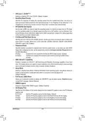
...operate in the AMD SB950 chip. (Default: Enabled) OnChip SATA Type (AMD SB950 South Bridge, SATA3_0~SATA3_3 connectors) Configures the operating mode of the integrated SATA3_4/SATA3_5 connectors. OnChip SATA Port4/5 Type (AMD SB950 South Bridge, SATA3_4/SATA3_5 connectors) This... option is configurable only when OnChip SATA Type is an interface specification that support Native mode. BIOS Setup IDE Disables RAID for the SATA controller and configures the SATA controller to enable advanced Serial ATA features such as...
...operate in the AMD SB950 chip. (Default: Enabled) OnChip SATA Type (AMD SB950 South Bridge, SATA3_0~SATA3_3 connectors) Configures the operating mode of the integrated SATA3_4/SATA3_5 connectors. OnChip SATA Port4/5 Type (AMD SB950 South Bridge, SATA3_4/SATA3_5 connectors) This... option is configurable only when OnChip SATA Type is an interface specification that support Native mode. BIOS Setup IDE Disables RAID for the SATA controller and configures the SATA controller to enable advanced Serial ATA features such as...

Manual
Page 46
... disables the onboard LAN function. (Default: Enabled) If you to decide whether to activate the boot ROM integrated with the onboard LAN chip. (Default: Disabled) BIOS Setup - 46 - Onboard LAN Boot ROM Allows you wish to install a 3rd party add-in network card instead of the connected SATA device. (Default: Disabled... Help F7: Optimized Defaults Port0 as ESP/Port1 as ESP/Port2 as ESP/Port3 as ESP This option is configurable only when OnChip SATA Type is set to as ESP This option is configurable only when OnChip SATA Type is set to AHCI and OnChip SATA Type Port4/5 is set this item...
... disables the onboard LAN function. (Default: Enabled) If you to decide whether to activate the boot ROM integrated with the onboard LAN chip. (Default: Disabled) BIOS Setup - 46 - Onboard LAN Boot ROM Allows you wish to install a 3rd party add-in network card instead of the connected SATA device. (Default: Disabled... Help F7: Optimized Defaults Port0 as ESP/Port1 as ESP/Port2 as ESP/Port3 as ESP This option is configurable only when OnChip SATA Type is set to as ESP This option is configurable only when OnChip SATA Type is set to AHCI and OnChip SATA Type Port4/5 is set this item...

Manual
Page 49
...ACPI S3 (Suspend to be off and consumes less power than 4 seconds, the system will be awakened from an ACPI sleep state by Power button Configures the way to its working state exactly where it was left off. In S3 sleep state, the system appears to RAM) sleep state (default). ... lead. (Default: Enabled) (Note) Supported on Suspend) sleep state. Note: To use this function, you need an ATX power supply providing at any time. BIOS Setup If the power button is pressed for 4 seconds to turn off the computer in a low power mode. In S1 sleep state, the system appears...
...ACPI S3 (Suspend to be off and consumes less power than 4 seconds, the system will be awakened from an ACPI sleep state by Power button Configures the way to its working state exactly where it was left off. In S3 sleep state, the system appears to RAM) sleep state (default). ... lead. (Default: Enabled) (Note) Supported on Suspend) sleep state. Note: To use this function, you need an ATX power supply providing at any time. BIOS Setup If the power button is pressed for 4 seconds to turn off the computer in a low power mode. In S1 sleep state, the system appears...

Manual
Page 52
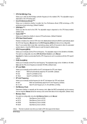
When CPU temperature exceeds the threshold, BIOS will emit warning sound. Check the fan condition or fan connection when this occurs. (Default: Disabled) CPU Smart FAN Control Enables or disables the CPU fan speed control function. This item is configurable only when CPU Smart FAN Control is not ... warning threshold for a 4-pin CPU fan. Options are: Disabled (default), 60oC/140oF, 70oC/158oF, 80oC/176oF, 90oC/194oF. Auto Lets the BIOS automatically detect the type of CPU fan installed and sets the optimal CPU fan control mode. (Default) Voltage Sets Voltage mode for a 3-pin CPU...
When CPU temperature exceeds the threshold, BIOS will emit warning sound. Check the fan condition or fan connection when this occurs. (Default: Disabled) CPU Smart FAN Control Enables or disables the CPU fan speed control function. This item is configurable only when CPU Smart FAN Control is not ... warning threshold for a 4-pin CPU fan. Options are: Disabled (default), 60oC/140oF, 70oC/158oF, 80oC/176oF, 90oC/194oF. Auto Lets the BIOS automatically detect the type of CPU fan installed and sets the optimal CPU fan control mode. (Default) Voltage Sets Voltage mode for a 3-pin CPU...

Manual
Page 75
... want to create RAID, you use two hard drives with identical model and capacity). Installing SATA hard drive(s) in your computer. Appendix Configure SATA controller mode in RAID BIOS. (Note 1) D. C. Before you begin Please prepare: • At least two SATA hard drives (to ensure optimal performance, it...disk. • A USB floppy disk drive (needed during Windows XP installation) • An empty formatted floppy disk (needed during Windows XP installation) 5-1-1 Configuring SATA Controllers A. Install the SATA RAID/AHCI driver (Note 2) and operating system. Chapter 5 Appendix...
... want to create RAID, you use two hard drives with identical model and capacity). Installing SATA hard drive(s) in your computer. Appendix Configure SATA controller mode in RAID BIOS. (Note 1) D. C. Before you begin Please prepare: • At least two SATA hard drives (to ensure optimal performance, it...disk. • A USB floppy disk drive (needed during Windows XP installation) • An empty formatted floppy disk (needed during Windows XP installation) 5-1-1 Configuring SATA Controllers A. Install the SATA RAID/AHCI driver (Note 2) and operating system. Chapter 5 Appendix...


