
Manual
Page 3
Example: All rights reserved. No part of this manual may be made by any form or by GIGABYTE without GIGABYTE's prior written permission. For product-related information, check on our website at: http://www.gigabyte.com Identifying Your Motherboard Revision The revision number on your ... Classifications In order to assist in the use of this manual are legally registered to the specifications and features in this manual may be reproduced, copied, translated, transmitted, or published in this product, GIGABYTE provides the following types of documentations: For quick...
Example: All rights reserved. No part of this manual may be made by any form or by GIGABYTE without GIGABYTE's prior written permission. For product-related information, check on our website at: http://www.gigabyte.com Identifying Your Motherboard Revision The revision number on your ... Classifications In order to assist in the use of this manual are legally registered to the specifications and features in this manual may be reproduced, copied, translated, transmitted, or published in this product, GIGABYTE provides the following types of documentations: For quick...

Manual
Page 5
Chapter 3 Drivers Installation 57 3-1 Installing Chipset Drivers 57 3-2 Application Software 58 3-3 Technical Manuals 58 3-4 Contact...59 3-5 System...59 3-6 Download Center 60 3-7 New Utilities...60 Chapter 4 Unique Features 61 4-1 Xpress Recovery2 61 4-2 BIOS Update Utilities 64 4-2-1 Updating the BIOS ...
Chapter 3 Drivers Installation 57 3-1 Installing Chipset Drivers 57 3-2 Application Software 58 3-3 Technical Manuals 58 3-4 Contact...59 3-5 System...59 3-6 Download Center 60 3-7 New Utilities...60 Chapter 4 Unique Features 61 4-1 Xpress Recovery2 61 4-2 BIOS Update Utilities 64 4-2-1 Updating the BIOS ...
Manual
Page 6
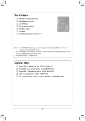
The box contents are for reference only. Box Contents GA-990FXA-UD3 motherboard Motherboard driver disk User's Manual Quick Installation Guide Two SATA cables I/O Shield One 2-Way SLI bridge connector (Note) (Note ) To enable NVIDIA SLI technology, you obtain. Optional ...COM port cable (Part No. 12CF1-1CM001-3*R) 3.5" Front Panel with 2 USB 3.0/2.0 ports (Part No. 12CR1-FPX582-0*R) - 6 - For more details, please go to GIGABYTE's website. • The box contents above are subject to change without notice. • The motherboard image is for reference only and the actual items shall...
The box contents are for reference only. Box Contents GA-990FXA-UD3 motherboard Motherboard driver disk User's Manual Quick Installation Guide Two SATA cables I/O Shield One 2-Way SLI bridge connector (Note) (Note ) To enable NVIDIA SLI technology, you obtain. Optional ...COM port cable (Part No. 12CF1-1CM001-3*R) 3.5" Front Panel with 2 USB 3.0/2.0 ports (Part No. 12CR1-FPX582-0*R) - 6 - For more details, please go to GIGABYTE's website. • The box contents above are subject to change without notice. • The motherboard image is for reference only and the actual items shall...
Manual
Page 9
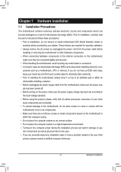
Prior to installation, carefully read the user's manual and follow these procedures: • Prior to installation, do not allow screws to come in contact with the motherboard circuit or its components. • Make ...
Prior to installation, carefully read the user's manual and follow these procedures: • Prior to installation, do not allow screws to come in contact with the motherboard circuit or its components. • Make ...
Manual
Page 15
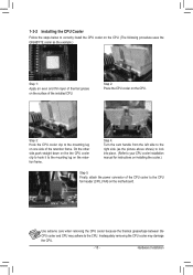
... the steps below to correctly install the CPU cooler on the CPU. (The following procedure uses the GIGABYTE cooler as the picture above shows) to lock into place. (Refer to your CPU cooler installation manual for instructions on installing the cooler.) Step 5: Finally, attach the power connector of the CPU cooler to...
... the steps below to correctly install the CPU cooler on the CPU. (The following procedure uses the GIGABYTE cooler as the picture above shows) to lock into place. (Refer to your CPU cooler installation manual for instructions on installing the cooler.) Step 5: Finally, attach the power connector of the CPU cooler to...
Manual
Page 18
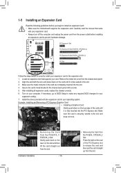
... BIOS changes for your computer. 1-5 Installing an Expansion Card Read the following guidelines before installing an expansion card to prevent hardware damage. Carefully read the manual that supports your expansion card. • Always turn off the computer and unplug the power cord from the PCIEX16_1/ PCIEX16_2 Slot: Gently push back on...
... BIOS changes for your computer. 1-5 Installing an Expansion Card Read the following guidelines before installing an expansion card to prevent hardware damage. Carefully read the manual that supports your expansion card. • Always turn off the computer and unplug the power cord from the PCIEX16_1/ PCIEX16_2 Slot: Gently push back on...
Manual
Page 19
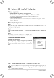
... slot. Browse to Performance\AMD CrossFireX Configurations and ensure the Enable CrossFireX™ check box is recommended (Refer to the manual that came with two PCI Express x16 slots and correct driver - Hardware Installation A CrossFireX-supported motherboard with your graphics cards. Refer ...to the manual of your graphics cards for enabling CrossFireX technology may be needed or not depending on top of identical brand and chip and ...
... slot. Browse to Performance\AMD CrossFireX Configurations and ensure the Enable CrossFireX™ check box is recommended (Refer to the manual that came with two PCI Express x16 slots and correct driver - Hardware Installation A CrossFireX-supported motherboard with your graphics cards. Refer ...to the manual of your graphics cards for enabling CrossFireX technology may be needed or not depending on top of identical brand and chip and ...
Manual
Page 26
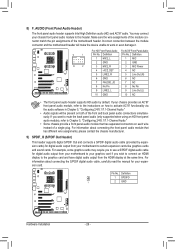
...(H) For HD Front Panel Audio: For AC'97 Front Panel Audio: 9 1 Pin No. For information about connecting the S/PDIF digital audio cable, carefully read the manual for your motherboard to work or even damage it. Pin No. Make sure the wire assignments of the module connector match the pin assignments of...
...(H) For HD Front Panel Audio: For AC'97 Front Panel Audio: 9 1 Pin No. For information about connecting the S/PDIF digital audio cable, carefully read the manual for your motherboard to work or even damage it. Pin No. Make sure the wire assignments of the module connector match the pin assignments of...
Manual
Page 29
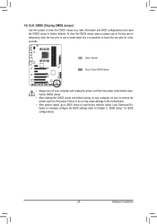
... so may cause damage to the motherboard. •• After system restart, go to BIOS Setup to load factory defaults (select Load Optimized Defaults) or manually configure the BIOS settings (refer to factory defaults. 14) CLR_CMOS (Clearing CMOS Jumper) Use this jumper to clear the CMOS values (e.g.
... so may cause damage to the motherboard. •• After system restart, go to BIOS Setup to load factory defaults (select Load Optimized Defaults) or manually configure the BIOS settings (refer to factory defaults. 14) CLR_CMOS (Clearing CMOS Jumper) Use this jumper to clear the CMOS values (e.g.
Manual
Page 36
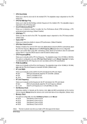
...clock as required. Important It is present only when you to 500 MHz. Auto lets BIOS automatically set the frequency for the installed CPU. Manual allows the CPU Frequency (MHz) item below to be configurable. (Default: Auto) Memory Clock This option is configurable only when Set Memory Clock...Memory Clock to X5.33. Allows you alter the ratio for automated system reboot, or clear the CMOS values to reset the board to manually set the memory clock. The adjustable range is set in accordance with the CPU specifications. Auto BIOS will automatically adjust the HT Link ...
...clock as required. Important It is present only when you to 500 MHz. Auto lets BIOS automatically set the frequency for the installed CPU. Manual allows the CPU Frequency (MHz) item below to be configurable. (Default: Auto) Memory Clock This option is configurable only when Set Memory Clock...Memory Clock to X5.33. Allows you alter the ratio for automated system reboot, or clear the CMOS values to reset the board to manually set the memory clock. The adjustable range is set in accordance with the CPU specifications. Auto BIOS will automatically adjust the HT Link ...

Manual
Page 38
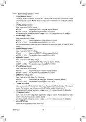
Unganged Sets memory control mode to two single-channel. (Default) DDR3 Timing Items Manual allows all DDR3 Timing items below to single dual-channel. Row Precharge Time Options are : Auto (default), 11T~42T. Row Cycle Time Options are : Auto (... are : Auto (default), 5T~12T. Precharge Time Options are : Auto (default), 1T, 2T. Ganged Sets memory control mode to be configurable. Options are: Auto (default), Manual. 1T/2T Command Timing Options are : Auto (default), 4T~7T. TwTr Command Delay Options are : Auto (default), 5T~8T, 10T, 12T. RAS to CAS R/W Delay...
Unganged Sets memory control mode to two single-channel. (Default) DDR3 Timing Items Manual allows all DDR3 Timing items below to single dual-channel. Row Precharge Time Options are : Auto (default), 11T~42T. Row Cycle Time Options are : Auto (... are : Auto (default), 5T~12T. Precharge Time Options are : Auto (default), 1T, 2T. Ganged Sets memory control mode to be configurable. Options are: Auto (default), Manual. 1T/2T Command Timing Options are : Auto (default), 4T~7T. TwTr Command Delay Options are : Auto (default), 5T~8T, 10T, 12T. RAS to CAS R/W Delay...
Manual
Page 40
...1.325V to 2.435V. Normal Supplies the North Bridge voltage as required. (Default) 0.865V ~ 1.9750V The adjustable range is from 0.725V to 1.835V. Manual allows all voltage control items below to be configurable. (Default: Auto) CPU PLL Voltage Control Allows you to set the CPU PLL voltage. Normal Supplies... of the memory. Auto lets the BIOS automatically set the system voltages. ******** System Voltage Optimized ******** System Voltage Control Determines whether to manually set the system voltages as required. Auto sets the CPU North Bridge VID voltage as required.
...1.325V to 2.435V. Normal Supplies the North Bridge voltage as required. (Default) 0.865V ~ 1.9750V The adjustable range is from 0.725V to 1.835V. Manual allows all voltage control items below to be configurable. (Default: Auto) CPU PLL Voltage Control Allows you to set the CPU PLL voltage. Normal Supplies... of the memory. Auto lets the BIOS automatically set the system voltages. ******** System Voltage Optimized ******** System Voltage Control Determines whether to manually set the system voltages as required. Auto sets the CPU North Bridge VID voltage as required.
Manual
Page 44
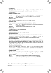
...disables CPU Core 1/2/3/4/5. (Default: Enabled) Hard Disk Boot Priority Specifies the sequence of cores available depends on the CPU being used). (Default) Manual Allows you enter BIOS Setup. Password Check Specifies whether a password is present only when you install a CPU that supports this item to EFI...and for entering the BIOS Setup program. (Note) This item is required every time the system boots, or only when you to manually enable/disable CPU Core 1/2/3/4/5. CPU Unlock (Note) Allows you to determine whether unlock hidden CPU cores. (Default: Disabled) CPU ...
...disables CPU Core 1/2/3/4/5. (Default: Enabled) Hard Disk Boot Priority Specifies the sequence of cores available depends on the CPU being used). (Default) Manual Allows you enter BIOS Setup. Password Check Specifies whether a password is present only when you install a CPU that supports this item to EFI...and for entering the BIOS Setup program. (Note) This item is required every time the system boots, or only when you to manually enable/disable CPU Core 1/2/3/4/5. CPU Unlock (Note) Allows you to determine whether unlock hidden CPU cores. (Default: Disabled) CPU ...
Manual
Page 57
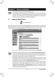
...click the Install All button and "Xpress Install" will install all of the drivers, a dialog box will appear asking whether to install new GIGABYTE utilities. After the system restart, "Xpress Install" will continue to install other drivers. • After "Xpress Install" installs all the ...recommended drivers. Or click Install Single Items to manually select the drivers you want to manually select the utilities to install on the Application Software page later. • For USB 2.0 driver support under the...
...click the Install All button and "Xpress Install" will install all of the drivers, a dialog box will appear asking whether to install new GIGABYTE utilities. After the system restart, "Xpress Install" will continue to install other drivers. • After "Xpress Install" installs all the ...recommended drivers. Or click Install Single Items to manually select the drivers you want to manually select the utilities to install on the Application Software page later. • For USB 2.0 driver support under the...

Manual
Page 58
3-2 Application Software This page displays all the utilities and applications that GIGABYTE develops and some free software. Drivers Installation - 58 - You can click the Install button on the right of an item to install it. 3-3 Technical Manuals This page provides GIGABYTE's application guides, content descriptions for this driver disk, and the motherboard manuals.
3-2 Application Software This page displays all the utilities and applications that GIGABYTE develops and some free software. Drivers Installation - 58 - You can click the Install button on the right of an item to install it. 3-3 Technical Manuals This page provides GIGABYTE's application guides, content descriptions for this driver disk, and the motherboard manuals.
Manual
Page 64
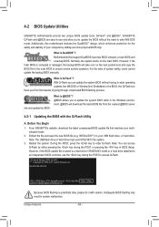
...the backup BIOS will download the latest BIOS file from the hassles of system safety, users cannot update the backup BIOS manually. 4-2 BIOS Update Utilities GIGABYTE motherboards provide two unique BIOS update tools, Q-Flash™ and @BIOS™. What is DualBIOS™? What is...the system BIOS while in system malfunction. Before You Begin 1. Embedded in the BIOS, the Q-Flash tool frees you to ensure normal system operation. GA-990FXA-UD3 D4 . . . . : BIOS Setup : XpressRecovery2 : Boot Menu : Qflash 04/27/2011-RD990-SB950-7A66FG06C-00 Because BIOS flashing is ...
...the backup BIOS will download the latest BIOS file from the hassles of system safety, users cannot update the backup BIOS manually. 4-2 BIOS Update Utilities GIGABYTE motherboards provide two unique BIOS update tools, Q-Flash™ and @BIOS™. What is DualBIOS™? What is...the system BIOS while in system malfunction. Before You Begin 1. Embedded in the BIOS, the Q-Flash tool frees you to ensure normal system operation. GA-990FXA-UD3 D4 . . . . : BIOS Setup : XpressRecovery2 : Boot Menu : Qflash 04/27/2011-RD990-SB950-7A66FG06C-00 Because BIOS flashing is ...

Manual
Page 67
...cause your system not to boot. - 67 - Failure to be flashed matches your motherboard is not present on the @BIOS server site, please manually download the BIOS update file from an inadequate BIOS flashing. If the BIOS update file for example, avoid a power loss or switching off the ...automatically load BIOS defaults after BIOS update and after updating the BIOS. Update the BIOS Using the Internet Update Function: Click Update BIOS from GIGABYTE Server, select the @BIOS server site closest to your location and then download the BIOS file that the BIOS file to do NOT interrupt...
...cause your system not to boot. - 67 - Failure to be flashed matches your motherboard is not present on the @BIOS server site, please manually download the BIOS update file from an inadequate BIOS flashing. If the BIOS update file for example, avoid a power loss or switching off the ...automatically load BIOS defaults after BIOS update and after updating the BIOS. Update the BIOS Using the Internet Update Function: Click Update BIOS from GIGABYTE Server, select the @BIOS server site closest to your location and then download the BIOS file that the BIOS file to do NOT interrupt...

Manual
Page 78
...Micro Devices, Inc. LD No LD Name LD 1 Logical Drive 1 [ LD Define Menu ] RAID Mode Drv RAID 0 0 Stripe Block Gigabyte Boundary Read Policy 64 KB ON Read Ahead Initialization ON Write Policy WriteBack [ Drives Assignments ] Port:ID 01:00 02:00 Drive Model WDC...N N [[KKeeyyssAAvvaailialabblele]] [h] Up [i] Down [PaUp/PaDn] Switch Page [Space] Change Option [Ctrl+Y] Save [ESC] Exit Figure 5 Appendix - 78 - Create Arrays Manually To create a new array, press to access the LD Define Menu. To create an array, press to enter the LD View Menu window (Figure 4). Option...
...Micro Devices, Inc. LD No LD Name LD 1 Logical Drive 1 [ LD Define Menu ] RAID Mode Drv RAID 0 0 Stripe Block Gigabyte Boundary Read Policy 64 KB ON Read Ahead Initialization ON Write Policy WriteBack [ Drives Assignments ] Port:ID 01:00 02:00 Drive Model WDC...N N [[KKeeyyssAAvvaailialabblele]] [h] Up [i] Down [PaUp/PaDn] Switch Page [Space] Change Option [Ctrl+Y] Save [ESC] Exit Figure 5 Appendix - 78 - Create Arrays Manually To create a new array, press to access the LD Define Menu. To create an array, press to enter the LD View Menu window (Figure 4). Option...

Manual
Page 94
... drive to select it and click the Submit button to begin the rebuild. Step 2: The screen will display as Done. • Manually Rebuilding RAID 1 in the Operating System You can manually rebuild a RAID 1 array without setting the new hard drive as a Spare drive in the RAID setup utility first. Step 3: Make sure...
... drive to select it and click the Submit button to begin the rebuild. Step 2: The screen will display as Done. • Manually Rebuilding RAID 1 in the Operating System You can manually rebuild a RAID 1 array without setting the new hard drive as a Spare drive in the RAID setup utility first. Step 3: Make sure...

Manual
Page 95
... the audio driver, the HD Audio Manager icon will be simultaneously processed. HD Audio features multistreaming capabilities that allow multiple audio streams (in jack and manually configure the jack for multi-channel speaker configurations. • 2-channel audio: Headphone or Line out. • 4-channel audio: Front speaker out and Side speaker out...
... the audio driver, the HD Audio Manager icon will be simultaneously processed. HD Audio features multistreaming capabilities that allow multiple audio streams (in jack and manually configure the jack for multi-channel speaker configurations. • 2-channel audio: Headphone or Line out. • 4-channel audio: Front speaker out and Side speaker out...


