
Manual
Page 3
.... For product-related information, check on our website at: http://www.gigabyte.com Identifying Your Motherboard Revision The revision number on your motherboard revision before updating motherboard BIOS, drivers, or when looking for technical information. Example: Disclaimer Information in... this manual may be made by GIGABYTE without GIGABYTE's prior written permission. Changes to assist in any means without...
.... For product-related information, check on our website at: http://www.gigabyte.com Identifying Your Motherboard Revision The revision number on your motherboard revision before updating motherboard BIOS, drivers, or when looking for technical information. Example: Disclaimer Information in... this manual may be made by GIGABYTE without GIGABYTE's prior written permission. Changes to assist in any means without...
Manual
Page 4
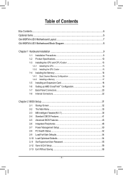
Table of Contents Box Contents...6 Optional Items...6 GA-990FXA-UD3 Motherboard Layout 7 GA-990FXA-UD3 Motherboard Block Diagram 8 Chapter 1 Hardware Installation 9 1-1 Installation Precautions 9 1-2 Product Specifications 10 1-3 Installing the CPU and CPU ...™ Configuration 19 1-7 Back Panel Connectors 20 1-8 Internal Connectors 22 Chapter 2 BIOS Setup 31 2-1 Startup Screen 32 2-2 The Main Menu 33 2-3 MB Intelligent Tweaker(M.I.T 35 2-4 Standard CMOS Features 41 2-5 Advanced BIOS Features 43 2-6 Integrated Peripherals 46 2-7 Power Management Setup 50 2-8 PC Health Status...
Table of Contents Box Contents...6 Optional Items...6 GA-990FXA-UD3 Motherboard Layout 7 GA-990FXA-UD3 Motherboard Block Diagram 8 Chapter 1 Hardware Installation 9 1-1 Installation Precautions 9 1-2 Product Specifications 10 1-3 Installing the CPU and CPU ...™ Configuration 19 1-7 Back Panel Connectors 20 1-8 Internal Connectors 22 Chapter 2 BIOS Setup 31 2-1 Startup Screen 32 2-2 The Main Menu 33 2-3 MB Intelligent Tweaker(M.I.T 35 2-4 Standard CMOS Features 41 2-5 Advanced BIOS Features 43 2-6 Integrated Peripherals 46 2-7 Power Management Setup 50 2-8 PC Health Status...

Manual
Page 5
... 58 3-4 Contact...59 3-5 System...59 3-6 Download Center 60 3-7 New Utilities...60 Chapter 4 Unique Features 61 4-1 Xpress Recovery2 61 4-2 BIOS Update Utilities 64 4-2-1 Updating the BIOS with the Q-Flash Utility 64 4-2-2 Updating the BIOS with the @BIOS Utility 67 4-3 EasyTune 6...68 4-4 Easy Energy Saver 69 4-5 Q-Share...71 4-6 SMART Recovery 72 4-7 Auto Green...73 4-8 Cloud OC...
... 58 3-4 Contact...59 3-5 System...59 3-6 Download Center 60 3-7 New Utilities...60 Chapter 4 Unique Features 61 4-1 Xpress Recovery2 61 4-2 BIOS Update Utilities 64 4-2-1 Updating the BIOS with the Q-Flash Utility 64 4-2-2 Updating the BIOS with the @BIOS Utility 67 4-3 EasyTune 6...68 4-4 Easy Energy Saver 69 4-5 Q-Share...71 4-6 SMART Recovery 72 4-7 Auto Green...73 4-8 Cloud OC...
Manual
Page 6
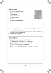
Box Contents GA-990FXA-UD3 motherboard Motherboard driver disk User's Manual Quick Installation Guide Two SATA cables I/O Shield One 2-Way SLI bridge connector (Note) (Note ) To enable NVIDIA SLI technology, ... No. 12CF1-1IE008-0*R) COM port cable (Part No. 12CF1-1CM001-3*R) 3.5" Front Panel with 2 USB 3.0/2.0 ports (Part No. 12CR1-FPX582-0*R) - 6 - For more details, please go to GIGABYTE's website. • The box contents above are subject to change without notice. • The motherboard image is for reference only and the actual items shall...
Box Contents GA-990FXA-UD3 motherboard Motherboard driver disk User's Manual Quick Installation Guide Two SATA cables I/O Shield One 2-Way SLI bridge connector (Note) (Note ) To enable NVIDIA SLI technology, ... No. 12CF1-1IE008-0*R) COM port cable (Part No. 12CF1-1CM001-3*R) 3.5" Front Panel with 2 USB 3.0/2.0 ports (Part No. 12CR1-FPX582-0*R) - 6 - For more details, please go to GIGABYTE's website. • The box contents above are subject to change without notice. • The motherboard image is for reference only and the actual items shall...
Manual
Page 8
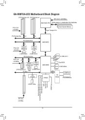
GA-990FXA-UD3 Motherboard Block Diagram 2 PCI Express x16 2 PCI Express x4 CPU CLK+/- (200 MHz) AM3+/AM3 CPU DDR3 2000(O.C.)/1866/1600/1333/1066 MHz PCIe CLK (... x1 (100 MHz) x1 Realtek RTL8111E x1 Etron EJ168 RJ45 2 PCI Express x1 2 USB 3.0/2.0 PCI Bus LAN VIA VT6308 AMD SB950 CODEC 14 USB 2.0/1.1 Dual BIOS 6 SATA 6Gb/s LPC Bus iTE IT8720 COM Port PS/2 KB/Mouse 2 IEEE 1394a Surround Speaker Out Center/Subwoofer Speaker Out Side Speaker Out MIC Line...
GA-990FXA-UD3 Motherboard Block Diagram 2 PCI Express x16 2 PCI Express x4 CPU CLK+/- (200 MHz) AM3+/AM3 CPU DDR3 2000(O.C.)/1866/1600/1333/1066 MHz PCIe CLK (... x1 (100 MHz) x1 Realtek RTL8111E x1 Etron EJ168 RJ45 2 PCI Express x1 2 USB 3.0/2.0 PCI Bus LAN VIA VT6308 AMD SB950 CODEC 14 USB 2.0/1.1 Dual BIOS 6 SATA 6Gb/s LPC Bus iTE IT8720 COM Port PS/2 KB/Mouse 2 IEEE 1394a Surround Speaker Out Center/Subwoofer Speaker Out Side Speaker Out MIC Line...

Manual
Page 12
...;Š 2 x 32 Mbit flash ŠŠ Use of licensed AWARD BIOS ŠŠ Support for DualBIOS™ ŠŠ PnP 1.0a, DMI 2.0, SM BIOS 2.4, ACPI 1.0b Unique Features ŠŠ Support for @BIOS ŠŠ Support for Q-Flash ŠŠ Support for Xpress BIOS Rescue ŠŠ Support for Download Center ŠŠ Support...
...;Š 2 x 32 Mbit flash ŠŠ Use of licensed AWARD BIOS ŠŠ Support for DualBIOS™ ŠŠ PnP 1.0a, DMI 2.0, SM BIOS 2.4, ACPI 1.0b Unique Features ŠŠ Support for @BIOS ŠŠ Support for Q-Flash ŠŠ Support for Xpress BIOS Rescue ŠŠ Support for Download Center ŠŠ Support...
Manual
Page 16
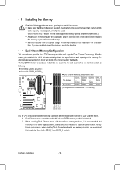
After the memory is installed, the BIOS will double the original memory bandwidth. DS/SS DS/SS DDR3_2 DS/SS - When enabling Dual Channel mode with two memory modules, we recommend that ... direction. 1-4-1 Dual Channel Memory Configuration This motherboard provides four DDR3 memory sockets and supports Dual Channel Technology. The four DDR3 memory sockets are unable to GIGABYTE's website for optimum performance. DS/SS (SS=Single-Sided, DS=Double-Sided, "- -"=No Memory) DDR3_4 DDR3_2 DDR3_3 DDR3_1 Due to CPU limitations, read the following...
After the memory is installed, the BIOS will double the original memory bandwidth. DS/SS DS/SS DDR3_2 DS/SS - When enabling Dual Channel mode with two memory modules, we recommend that ... direction. 1-4-1 Dual Channel Memory Configuration This motherboard provides four DDR3 memory sockets and supports Dual Channel Technology. The four DDR3 memory sockets are unable to GIGABYTE's website for optimum performance. DS/SS (SS=Single-Sided, DS=Double-Sided, "- -"=No Memory) DDR3_4 DDR3_2 DDR3_3 DDR3_1 Due to CPU limitations, read the following...
Manual
Page 18
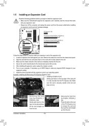
... your expansion card(s). 7. After installing all expansion cards, replace the chassis cover(s). 6. Install the driver provided with a screw. 5. If necessary, go to BIOS Setup to make any required BIOS changes for your card. 1-5 Installing an Expansion Card Read the following guidelines before installing an expansion card to prevent hardware damage. Secure the...
... your expansion card(s). 7. After installing all expansion cards, replace the chassis cover(s). 6. Install the driver provided with a screw. 5. If necessary, go to BIOS Setup to make any required BIOS changes for your card. 1-5 Installing an Expansion Card Read the following guidelines before installing an expansion card to prevent hardware damage. Secure the...

Manual
Page 25
.../Power/ Power Sleep LED Switch Speaker MSG+ MSG- The LED keeps blinking when the sys- If a problem is detected, the BIOS may issue beeps in different patterns to this header according to the speaker on the chassis that can detect if the chassis cover has... Off state or powered off your chassis front panel module to indicate the problem. When connecting your system using the power switch (refer to Chapter 2, "BIOS Setup," "Power Management Setup," for information about beep codes. •• HD (Hard Drive Activity LED, Blue) Connects to the power status indicator ...
.../Power/ Power Sleep LED Switch Speaker MSG+ MSG- The LED keeps blinking when the sys- If a problem is detected, the BIOS may issue beeps in different patterns to this header according to the speaker on the chassis that can detect if the chassis cover has... Off state or powered off your chassis front panel module to indicate the problem. When connecting your system using the power switch (refer to Chapter 2, "BIOS Setup," "Power Management Setup," for information about beep codes. •• HD (Hard Drive Activity LED, Blue) Connects to the power status indicator ...
Manual
Page 26
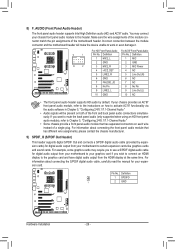
... 2 GND (H61M-D2) 10 2 3 MIC2_R 3 MIC Power 4 -ACZ_DET 4 NC 5 LINE2_R 5 Line Out (R) 6 GND 6 NC 7 FAUDIO_JD 7 NC 8 No Pin 8 No Pin 9 LINE2_L 9 Line Out (L) DB_PORT 10 BIOS Switcher (X58A-OC) GND 10 NC DIP 1 23 1 • The front panel audio header 1supports HD audio by expansion cards) for digital audio output from...
... 2 GND (H61M-D2) 10 2 3 MIC2_R 3 MIC Power 4 -ACZ_DET 4 NC 5 LINE2_R 5 Line Out (R) 6 GND 6 NC 7 FAUDIO_JD 7 NC 8 No Pin 8 No Pin 9 LINE2_L 9 Line Out (L) DB_PORT 10 BIOS Switcher (X58A-OC) GND 10 NC DIP 1 23 1 • The front panel audio header 1supports HD audio by expansion cards) for digital audio output from...
Manual
Page 27
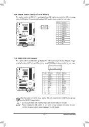
.... For pur- Definition 1 VBUS 11 D2+ 2 SSRX1- 12 D2- 3 SSRX1+ 13 GND 4 GND 14 SSTX2+ 5 SSTX1- 15 SSTX2- 6 SSTX1+ 16 GND 7 GND 17 SSRX2+ DB_PORT BIOS 8 D1- 18 SSRX2- 9 D1+ 19 VBUS 10 NC 20 No Pin When the system is in S4/S5 mode, only the USB ports routed to...
.... For pur- Definition 1 VBUS 11 D2+ 2 SSRX1- 12 D2- 3 SSRX1+ 13 GND 4 GND 14 SSTX2+ 5 SSTX1- 15 SSTX2- 6 SSTX1+ 16 GND 7 GND 17 SSRX2+ DB_PORT BIOS 8 D1- 18 SSRX2- 9 D1+ 19 VBUS 10 NC 20 No Pin When the system is in S4/S5 mode, only the USB ports routed to...
Manual
Page 29
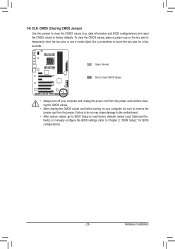
Open: Normal Short: Clear CMOS Values •• Always turn off your computer, be sure to touch the two pins for BIOS configurations). - 29 - To clear the CMOS values, place a jumper cap on your computer and unplug the power cord from the power outlet before.... Failure to do so may cause damage to the motherboard. •• After system restart, go to BIOS Setup to load factory defaults (select Load Optimized Defaults) or manually configure the BIOS settings (refer to clear the CMOS values (e.g. Hardware Installation 14) CLR_CMOS (Clearing CMOS Jumper) Use this jumper...
Open: Normal Short: Clear CMOS Values •• Always turn off your computer, be sure to touch the two pins for BIOS configurations). - 29 - To clear the CMOS values, place a jumper cap on your computer and unplug the power cord from the power outlet before.... Failure to do so may cause damage to the motherboard. •• After system restart, go to BIOS Setup to load factory defaults (select Load Optimized Defaults) or manually configure the BIOS settings (refer to clear the CMOS values (e.g. Hardware Installation 14) CLR_CMOS (Clearing CMOS Jumper) Use this jumper...
Manual
Page 30
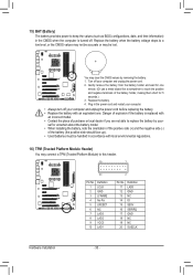
... up). • Used batteries must be lost. 1 You may connect a TPM (Trusted Platform Module) to keep the values (such as BIOS configurations, date, and time information) in the CMOS when the computer is replaced with local environmental regulations. DB_PORT 16) TPM (Trusted Platform Module....) F_AUDIO(H) 3. Replace the battery when the battery voltage drops to touch the positive and negative terminals of the battery holder, making them short for one . BIOS Switc 1 1 19 TPM w/housing 20 Pin No. 1 2 3 4 5 6 7 8 9 10 Definition LCLK GND LFRAME No Pin LRESET NC LAD3 LAD2...
... up). • Used batteries must be lost. 1 You may connect a TPM (Trusted Platform Module) to keep the values (such as BIOS configurations, date, and time information) in the CMOS when the computer is replaced with local environmental regulations. DB_PORT 16) TPM (Trusted Platform Module....) F_AUDIO(H) 3. Replace the battery when the battery voltage drops to touch the positive and negative terminals of the battery holder, making them short for one . BIOS Switc 1 1 19 TPM w/housing 20 Pin No. 1 2 3 4 5 6 7 8 9 10 Definition LCLK GND LFRAME No Pin LRESET NC LAD3 LAD2...
Manual
Page 31
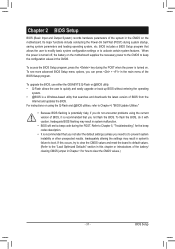
... current version of BIOS, it with caution. To access the BIOS Setup program, press the key during the POST when the power is recommended that you not alter the default settings (unless you not flash the BIOS. To upgrade the BIOS, use either the GIGABYTE Q-Flash or @BIOS utility. •... Q-Flash allows the user to quickly and easily upgrade or back up BIOS without entering the operating system. • @BIOS is recommended that you need to) to boot....
... current version of BIOS, it with caution. To access the BIOS Setup program, press the key during the POST when the power is recommended that you not alter the default settings (unless you not flash the BIOS. To upgrade the BIOS, use either the GIGABYTE Q-Flash or @BIOS utility. •... Q-Flash allows the user to quickly and easily upgrade or back up BIOS without entering the operating system. • @BIOS is recommended that you need to) to boot....
Manual
Page 32
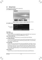
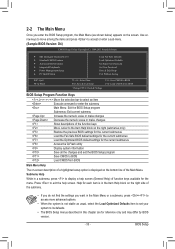
GA-990FXA-UD3 D4 . . . . : BIOS Setup : XpressRecovery2 : Boot Menu : Qflash 04/27/2011-RD990-SB950-7A66FG06C-00 Function Keys Function Keys Function Keys: : POST SCREEN Press the key to show the BIOS POST screen at system startup, refer to the instructions on the Full Screen LOGO Show item on BIOS...will still be used for one time only. 2-1 Startup Screen The following screens may appear when the computer boots. A. To show the BIOS POST screen. BIOS Setup - 32 - For more information, refer to Chapter 4, "Xpress Recovery2." : BOOT MENU Boot Menu allows you have ever entered ...
GA-990FXA-UD3 D4 . . . . : BIOS Setup : XpressRecovery2 : Boot Menu : Qflash 04/27/2011-RD990-SB950-7A66FG06C-00 Function Keys Function Keys Function Keys: : POST SCREEN Press the key to show the BIOS POST screen at system startup, refer to the instructions on the Full Screen LOGO Show item on BIOS...will still be used for one time only. 2-1 Startup Screen The following screens may appear when the computer boots. A. To show the BIOS POST screen. BIOS Setup - 32 - For more information, refer to Chapter 4, "Xpress Recovery2." : BOOT MENU Boot Menu allows you have ever entered ...
Manual
Page 33
...Without Saving ESC: Quit F8: Q-Flash Select Item F10: Save & Exit Setup Change CPU's Clock & Voltage F11: Save CMOS to BIOS F12: Load CMOS from BIOS BIOS Setup Program Function Keys Move the selection bar to select an item Execute command or enter the submenu Main Menu: Exit the...settings for the current submenus Access the Q-Flash utility Display system information Save all the changes and exit the BIOS Setup program Save CMOS to BIOS Load CMOS from BIOS Main Menu Help The on-screen description of a highlighted setup option is not stable as shown below) ...
...Without Saving ESC: Quit F8: Q-Flash Select Item F10: Save & Exit Setup Change CPU's Clock & Voltage F11: Save CMOS to BIOS F12: Load CMOS from BIOS BIOS Setup Program Function Keys Move the selection bar to select an item Execute command or enter the submenu Main Menu: Exit the...settings for the current submenus Access the Q-Flash utility Display system information Save all the changes and exit the BIOS Setup program Save CMOS to BIOS Load CMOS from BIOS Main Menu Help The on-screen description of a highlighted setup option is not stable as shown below) ...

Manual
Page 34
...First enter the profile name (to erase the default profile name, use the SPACE key) and then press to complete. F12: Load CMOS from BIOS If your CPU, memory, etc. Standard CMOS Features Use this menu to configure the system time and date, hard drive types, and the type... of errors that stop the system boot, etc. Advanced BIOS Features Use this menu to configure the device boot order, advanced features available on the CPU, and the primary display adapter. Integrated Peripherals Use...
...First enter the profile name (to erase the default profile name, use the SPACE key) and then press to complete. F12: Load CMOS from BIOS If your CPU, memory, etc. Standard CMOS Features Use this menu to configure the system time and date, hard drive types, and the type... of errors that stop the system boot, etc. Advanced BIOS Features Use this menu to configure the device boot order, advanced features available on the CPU, and the primary display adapter. Integrated Peripherals Use...
Manual
Page 35
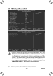
... settings. (Note) This item is for advanced users only and we recommend you made is dependent on your overall system configurations. If this feature. - 35 - BIOS Setup Core Performance Boost (Note) CPB Ratio (Note) Turbo CPB (Note) CPU Host Clock Control x CPU Frequency(MHz) PCIE Clock(MHz) HT Link Width HT...
... settings. (Note) This item is for advanced users only and we recommend you made is dependent on your overall system configurations. If this feature. - 35 - BIOS Setup Core Performance Boost (Note) CPB Ratio (Note) Turbo CPB (Note) CPU Host Clock Control x CPU Frequency(MHz) PCIE Clock(MHz) HT Link Width HT...
Manual
Page 36
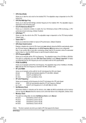
...the CPU and chipset. HT Link Frequency Allows you to manually set to Manual. X4.00 Sets Memory Clock to 500 MHz. BIOS Setup - 36 - Auto (default) allows the BIOS to enable the Core Performance Boost (CPB) technology, a CPU performance-boost technology. (Default: Enabled) CPB Ratio (Note) Allows...to 16 bit. The adjustable range is highly recommended that supports this feature. Manual allows the CPU Frequency (MHz) item below to Manual. Auto BIOS will automatically adjust the HT Link Width. (Default) 8 bit Sets HT Link Width to 8 bit. 16 bit Sets HT Link Width to...
...the CPU and chipset. HT Link Frequency Allows you to manually set to Manual. X4.00 Sets Memory Clock to 500 MHz. BIOS Setup - 36 - Auto (default) allows the BIOS to enable the Core Performance Boost (CPB) technology, a CPU performance-boost technology. (Default: Enabled) CPB Ratio (Note) Allows...to 16 bit. The adjustable range is highly recommended that supports this feature. Manual allows the CPU Frequency (MHz) item below to Manual. Auto BIOS will automatically adjust the HT Link Width. (Default) 8 bit Sets HT Link Width to 8 bit. 16 bit Sets HT Link Width to...

Manual
Page 37
... Move Enter: Select F5: Previous Values +/-/PU/PD: Value F10: Save F6: Fail-Safe Defaults - 37 - ESC: Exit F1: General Help F7: Optimized Defaults BIOS Setup
... Move Enter: Select F5: Previous Values +/-/PU/PD: Value F10: Save F6: Fail-Safe Defaults - 37 - ESC: Exit F1: General Help F7: Optimized Defaults BIOS Setup


