Manual
Page 7
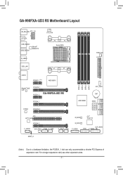
For a longer expansion card, use other expansion slots. - 7 - GA-990FXA-UD3 R5 Motherboard Layout KB_MS_USB ATX_12V OPTICAL USB_ESATA2 USB_ESATA1 Marvell® 88SE9172 R_USB30 USB_LAN CPU_FAN Socket AM3+ PWR_FAN ATX AUDIO PCIEX1_1 (Note) AMD 990FX Realtek® GbE LAN PCIEX16_1 PCIEX1_2 GA-990FXA-UD3 R5 PCIEX4_1 CODEC PCIEX16_2 DDR3_4 DDR3_2 DDR3_3 DDR3_1 AMD SB950 SYS_FAN1 BAT SATA3 45 23 01 PCI VIA...
For a longer expansion card, use other expansion slots. - 7 - GA-990FXA-UD3 R5 Motherboard Layout KB_MS_USB ATX_12V OPTICAL USB_ESATA2 USB_ESATA1 Marvell® 88SE9172 R_USB30 USB_LAN CPU_FAN Socket AM3+ PWR_FAN ATX AUDIO PCIEX1_1 (Note) AMD 990FX Realtek® GbE LAN PCIEX16_1 PCIEX1_2 GA-990FXA-UD3 R5 PCIEX4_1 CODEC PCIEX16_2 DDR3_4 DDR3_2 DDR3_3 DDR3_1 AMD SB950 SYS_FAN1 BAT SATA3 45 23 01 PCI VIA...
Manual
Page 12
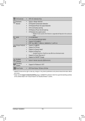
...OFF Charge Norton® Internet Security (OEM version) Support for Windows 8.1/8/7 Form Factor Š ATX Form Factor; 30.5cm x 24.4cm * GIGABYTE reserves the right to make any changes to check the supported operating system(s) for EasyTune * Available...fail warning CPU/System fan speed control * Whether the fan speed control function is supported will depend on GIGABYTE's website to the product specifications and product-related information without prior notice. * Please visit the Support &...Xpress Install Support for the software listed in EasyTune may differ by motherboard model.
...OFF Charge Norton® Internet Security (OEM version) Support for Windows 8.1/8/7 Form Factor Š ATX Form Factor; 30.5cm x 24.4cm * GIGABYTE reserves the right to make any changes to check the supported operating system(s) for EasyTune * Available...fail warning CPU/System fan speed control * Whether the fan speed control function is supported will depend on GIGABYTE's website to the product specifications and product-related information without prior notice. * Please visit the Support &...Xpress Install Support for the software listed in EasyTune may differ by motherboard model.
Manual
Page 22
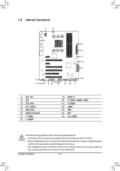
... sure the device cable has been securely attached to turn off the devices and your computer. 1-8 Internal Connectors 1 3 5 2 4 14 6 8 15 9 4 12 10 11 13 7 1) ATX_12V 2) ATX 3) CPU_FAN 4) SYS_FAN1/2 5) PWR_FAN 6) SATA3 0/1/2/3/4/5 7) F_PANEL 8) F_AUDIO 9) SPDIF_O 10) F_USB1/F_USB2/F_USB3 11) F_USB30 12) COMA 13) TPM 14) BAT 15) CLR_CMOS Read the following guidelines... sure your devices are compliant with the connectors you wish to connect. •• Before installing the devices, be sure to the connector on the motherboard.
... sure the device cable has been securely attached to turn off the devices and your computer. 1-8 Internal Connectors 1 3 5 2 4 14 6 8 15 9 4 12 10 11 13 7 1) ATX_12V 2) ATX 3) CPU_FAN 4) SYS_FAN1/2 5) PWR_FAN 6) SATA3 0/1/2/3/4/5 7) F_PANEL 8) F_AUDIO 9) SPDIF_O 10) F_USB1/F_USB2/F_USB3 11) F_USB30 12) COMA 13) TPM 14) BAT 15) CLR_CMOS Read the following guidelines... sure your devices are compliant with the connectors you wish to connect. •• Before installing the devices, be sure to the connector on the motherboard.
Manual
Page 23
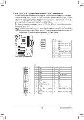
... withstand high power consumption be used (500W or greater). Hardware Installation If the 12V power connector is turned off and all the components on the motherboard. To meet expansion requirements, it is used that can lead to an unstable or unbootable system. 8 4 5 1 ATX_12V ATX_12V: Pin No. 1 2 3 4 5 6 7 8 Definition GND (...) GND (Only for 2x4-pin 12V) GND GND +12V (Only for 2x4-pin 12V) +12V (Only for 2x4-pin 12V) +12V +12V 12 24 1 13 ATX ATX: Pin No. 1 2 3 4 5 6 7 8 9 10 11 12 Definition Pin No. 3.3V 13 3.3V 14 GND 15 +5V 16 GND 17 +5V 18 GND 19 ...
... withstand high power consumption be used (500W or greater). Hardware Installation If the 12V power connector is turned off and all the components on the motherboard. To meet expansion requirements, it is used that can lead to an unstable or unbootable system. 8 4 5 1 ATX_12V ATX_12V: Pin No. 1 2 3 4 5 6 7 8 Definition GND (...) GND (Only for 2x4-pin 12V) GND GND +12V (Only for 2x4-pin 12V) +12V (Only for 2x4-pin 12V) +12V +12V 12 24 1 13 ATX ATX: Pin No. 1 2 3 4 5 6 7 8 9 10 11 12 Definition Pin No. 3.3V 13 3.3V 14 GND 15 +5V 16 GND 17 +5V 18 GND 19 ...
Manual
Page 93
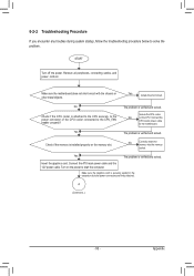
Yes The problem is verified and solved. Appendix Make sure the motherboard does not short-circuit with the chassis or other metal objects. Yes Isolate the short circuit. The problem is verified and solved. Turn on the ... problem is securely seated in the expansion slot and power connectors are firmly attached. Make sure the graphics card is verified and solved. Connect the ATX main power cable and the 12V power cable. Connect the CPU cooler power cable to the CPU securely. Check if the memory is attached to...
Yes The problem is verified and solved. Appendix Make sure the motherboard does not short-circuit with the chassis or other metal objects. Yes Isolate the short circuit. The problem is verified and solved. Turn on the ... problem is securely seated in the expansion slot and power connectors are firmly attached. Make sure the graphics card is verified and solved. Connect the ATX main power cable and the 12V power cable. Connect the CPU cooler power cable to the CPU securely. Check if the memory is attached to...


