Manual
Page 3
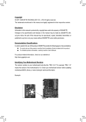
... registered to assist in this manual may be made by GIGABYTE without GIGABYTE's prior written permission. For product-related information, check on our website at: http://www.gigabyte.com Identifying Your Motherboard Revision The revision number on your motherboard revision before updating motherboard BIOS, drivers, or when looking for technical information. Example: Copyright ©...
... registered to assist in this manual may be made by GIGABYTE without GIGABYTE's prior written permission. For product-related information, check on our website at: http://www.gigabyte.com Identifying Your Motherboard Revision The revision number on your motherboard revision before updating motherboard BIOS, drivers, or when looking for technical information. Example: Copyright ©...
Manual
Page 4
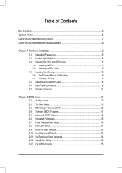
Table of Contents Box Contents...6 Optional Items...6 GA-970A-UD3 Motherboard Layout 7 GA-970A-UD3 Motherboard Block Diagram 8 Chapter 1 Hardware Installation 9 1-1 Installation Precautions 9 1-2 Product Specifications 10 1-3 Installing the CPU and CPU ... an Expansion Card 18 1-6 Back Panel Connectors 19 1-7 Internal Connectors 21 Chapter 2 BIOS Setup 31 2-1 Startup Screen 32 2-2 The Main Menu 33 2-3 MB Intelligent Tweaker(M.I.T 35 2-4 Standard CMOS Features 41 2-5 Advanced BIOS Features 43 2-6 Integrated Peripherals 45 2-7 Power Management Setup 49 2-8 PC Health Status ...
Table of Contents Box Contents...6 Optional Items...6 GA-970A-UD3 Motherboard Layout 7 GA-970A-UD3 Motherboard Block Diagram 8 Chapter 1 Hardware Installation 9 1-1 Installation Precautions 9 1-2 Product Specifications 10 1-3 Installing the CPU and CPU ... an Expansion Card 18 1-6 Back Panel Connectors 19 1-7 Internal Connectors 21 Chapter 2 BIOS Setup 31 2-1 Startup Screen 32 2-2 The Main Menu 33 2-3 MB Intelligent Tweaker(M.I.T 35 2-4 Standard CMOS Features 41 2-5 Advanced BIOS Features 43 2-6 Integrated Peripherals 45 2-7 Power Management Setup 49 2-8 PC Health Status ...
Manual
Page 5
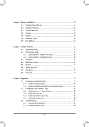
... 58 3-4 Contact...59 3-5 System...59 3-6 Download Center 60 3-7 New Utilities...60 Chapter 4 Unique Features 61 4-1 Xpress Recovery2 61 4-2 BIOS Update Utilities 64 4-2-1 Updating the BIOS with the Q-Flash Utility 64 4-2-2 Updating the BIOS with the @BIOS Utility 67 4-3 EasyTune 6...68 4-4 Easy Energy Saver 69 4-5 Q-Share...71 4-6 SMART Recovery 72 4-7 Auto Green...73 4-8 Cloud OC...
... 58 3-4 Contact...59 3-5 System...59 3-6 Download Center 60 3-7 New Utilities...60 Chapter 4 Unique Features 61 4-1 Xpress Recovery2 61 4-2 BIOS Update Utilities 64 4-2-1 Updating the BIOS with the Q-Flash Utility 64 4-2-2 Updating the BIOS with the @BIOS Utility 67 4-3 EasyTune 6...68 4-4 Easy Energy Saver 69 4-5 Q-Share...71 4-6 SMART Recovery 72 4-7 Auto Green...73 4-8 Cloud OC...
Manual
Page 8
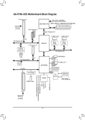
GA-970A-UD3 Motherboard Block Diagram 1 PCI Express x16 CPU CLK+/- (200 MHz) PCIe CLK (100 MHz) AM3+/AM3 CPU DDR3 2000(O.C.)/1866/1600/1333/1066 MHz Dual ... VIA VT6308 2 IEEE 1394a 2 USB 3.0/2.0 2 USB 3.0/2.0 AMD 970 Etron EJ168 Etron EJ168 x1 x1 PCI Express Bus 6 SATA 6Gb/s AMD SB950 CODEC 14 USB 2.0/1.1 Dual BIOS LPC Bus iTE IT8720 COM Port PS/2 KB/Mouse Surround Speaker Out Center/Subwoofer Speaker Out Side Speaker Out MIC Line Out Line In S/PDIF...
GA-970A-UD3 Motherboard Block Diagram 1 PCI Express x16 CPU CLK+/- (200 MHz) PCIe CLK (100 MHz) AM3+/AM3 CPU DDR3 2000(O.C.)/1866/1600/1333/1066 MHz Dual ... VIA VT6308 2 IEEE 1394a 2 USB 3.0/2.0 2 USB 3.0/2.0 AMD 970 Etron EJ168 Etron EJ168 x1 x1 PCI Express Bus 6 SATA 6Gb/s AMD SB950 CODEC 14 USB 2.0/1.1 Dual BIOS LPC Bus iTE IT8720 COM Port PS/2 KB/Mouse Surround Speaker Out Center/Subwoofer Speaker Out Side Speaker Out MIC Line Out Line In S/PDIF...

Manual
Page 11
Hardware Installation Internal Connectors Back Panel Connectors I/O Controller Hardware Monitor BIOS ŠŠ 1 x 24-pin ATX main power connector ŠŠ 1 x 8-pin ATX 12V power connector ŠŠ 6 x SATA 6Gb/s connectors ŠŠ 1 x CPU fan header &#... speed control function is supported will depend on the CPU/system cooler you install. ŠŠ 2 x 32 Mbit flash ŠŠ Use of licensed AWARD BIOS ŠŠ Support for DualBIOS™ ŠŠ PnP 1.0a, DMI 2.0, SM...
Hardware Installation Internal Connectors Back Panel Connectors I/O Controller Hardware Monitor BIOS ŠŠ 1 x 24-pin ATX main power connector ŠŠ 1 x 8-pin ATX 12V power connector ŠŠ 6 x SATA 6Gb/s connectors ŠŠ 1 x CPU fan header &#... speed control function is supported will depend on the CPU/system cooler you install. ŠŠ 2 x 32 Mbit flash ŠŠ Use of licensed AWARD BIOS ŠŠ Support for DualBIOS™ ŠŠ PnP 1.0a, DMI 2.0, SM...

Manual
Page 12
Hardware Installation - 12 - Unique Features ŠŠ Support for @BIOS ŠŠ Support for Q-Flash ŠŠ Support for Xpress BIOS Rescue ŠŠ Support for Download Center ŠŠ Support for Xpress Install ŠŠ Support for Xpress Recovery2 ŠŠ Support for EasyTune * Available ...
Hardware Installation - 12 - Unique Features ŠŠ Support for @BIOS ŠŠ Support for Q-Flash ŠŠ Support for Xpress BIOS Rescue ŠŠ Support for Download Center ŠŠ Support for Xpress Install ŠŠ Support for Xpress Recovery2 ŠŠ Support for EasyTune * Available ...
Manual
Page 16
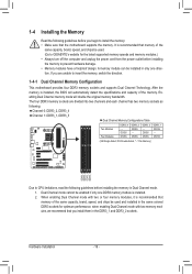
...mode with two memory modules, we recommend that memory of the same capacity, brand, speed, and chips be used . (Go to GIGABYTE's website for optimum performance. The four DDR3 memory sockets are unable to insert the memory, switch the direction. 1-4-1 Dual Channel Memory ... the following guidelines before installing the memory to prevent hardware damage. • Memory modules have a foolproof design. It is installed, the BIOS will double the original memory bandwidth. DS/SS DDR3_3 - 1-4 Installing the Memory Read the following guidelines before you begin to install the ...
...mode with two memory modules, we recommend that memory of the same capacity, brand, speed, and chips be used . (Go to GIGABYTE's website for optimum performance. The four DDR3 memory sockets are unable to insert the memory, switch the direction. 1-4-1 Dual Channel Memory ... the following guidelines before installing the memory to prevent hardware damage. • Memory modules have a foolproof design. It is installed, the BIOS will double the original memory bandwidth. DS/SS DDR3_3 - 1-4 Installing the Memory Read the following guidelines before you begin to install the ...
Manual
Page 18
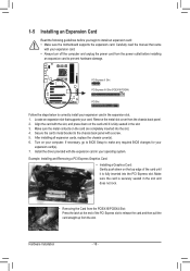
... - 18 - 1-5 Installing an Expansion Card Read the following guidelines before installing an expansion card to prevent hardware damage. If necessary, go to BIOS Setup to make any required BIOS changes for your operating system. Align the card with a screw. 5. Make sure the metal contacts on the card until it is fully seated...
... - 18 - 1-5 Installing an Expansion Card Read the following guidelines before installing an expansion card to prevent hardware damage. If necessary, go to BIOS Setup to make any required BIOS changes for your operating system. Align the card with a screw. 5. Make sure the metal contacts on the card until it is fully seated...

Manual
Page 24
...• SPEAK (Speaker, Orange): Connects to the speaker on the chassis front panel. The LED is on when the hard drive is detected, the BIOS may configure the way to turn off (S5). • PW (Power Switch, Red): Connects to the power switch on the chassis front panel. ...indicator on the chassis that can detect if the chassis cover has been removed. When connecting your system using the power switch (refer to Chapter 2, "BIOS Setup," "Power Management Setup," for information about beep codes. • HD (Hard Drive Activity LED, Blue) Connects to the hard drive activity ...
...• SPEAK (Speaker, Orange): Connects to the speaker on the chassis front panel. The LED is on when the hard drive is detected, the BIOS may configure the way to turn off (S5). • PW (Power Switch, Red): Connects to the power switch on the chassis front panel. ...indicator on the chassis that can detect if the chassis cover has been removed. When connecting your system using the power switch (refer to Chapter 2, "BIOS Setup," "Power Management Setup," for information about beep codes. • HD (Hard Drive Activity LED, Blue) Connects to the hard drive activity ...

Manual
Page 26
..., please contact the local dealer. Definition 1 VBUS 11 D2+ 2 SSRX1- 12 D2- 3 SSRX1+ 13 GND 4 GND 14 SSTX2+ 5 SSTX1- 15 SSTX2- 6 SSTX1+ 16 GND DB_PORT BIOS 7 GND 17 SSRX2+ 8 D1- 18 SSRX2- 9 D1+ 19 VBUS 10 NC 20 No Pin When the system is in S4/S5 mode, only the USB...
..., please contact the local dealer. Definition 1 VBUS 11 D2+ 2 SSRX1- 12 D2- 3 SSRX1+ 13 GND 4 GND 14 SSTX2+ 5 SSTX1- 15 SSTX2- 6 SSTX1+ 16 GND DB_PORT BIOS 7 GND 17 SSRX2+ 8 D1- 18 SSRX2- 9 D1+ 19 VBUS 10 NC 20 No Pin When the system is in S4/S5 mode, only the USB...

Manual
Page 28
...15 SB3V 16 SERIRQ 17 GND 18 NC 19 NC 20 SUSCLK 15) BAT (Battery) The battery provides power to keep the values (such as BIOS configurations, date, and time information) in the power cord and restart your computer. •• Always turn off . You may clear the ... with an equivalent one. Danger of the battery holder, making them short for one minute. (Or use a metal object like a screwdriver to this header. DB_PORT BIOS Switc 1 1 19 TPM w/housing 20 Pin No. 1 2 3 4 5 6 7 8 9 10 Definition LCLK GND LFRAME No Pin LRESET NC LAD3 LAD2 VCC3 LAD1 1 Voltage measurement ...
...15 SB3V 16 SERIRQ 17 GND 18 NC 19 NC 20 SUSCLK 15) BAT (Battery) The battery provides power to keep the values (such as BIOS configurations, date, and time information) in the power cord and restart your computer. •• Always turn off . You may clear the ... with an equivalent one. Danger of the battery holder, making them short for one minute. (Or use a metal object like a screwdriver to this header. DB_PORT BIOS Switc 1 1 19 TPM w/housing 20 Pin No. 1 2 3 4 5 6 7 8 9 10 Definition LCLK GND LFRAME No Pin LRESET NC LAD3 LAD2 VCC3 LAD1 1 Voltage measurement ...
Manual
Page 29
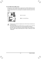
...sure to remove the jumper cap from the jumper. 16) CLR_CMOS (Clearing CMOS Jumper) Use this jumper to factory defaults. date information and BIOS configurations) and reset the CMOS values to clear the CMOS values (e.g. Failure to do so may cause damage to the motherboard. ••...; After system restart, go to BIOS Setup to load factory defaults (select Load Optimized Defaults) or manually configure the BIOS settings (refer to touch the two pins for BIOS configurations). - 29 - Open: Normal Short: Clear CMOS Values •• ...
...sure to remove the jumper cap from the jumper. 16) CLR_CMOS (Clearing CMOS Jumper) Use this jumper to factory defaults. date information and BIOS configurations) and reset the CMOS values to clear the CMOS values (e.g. Failure to do so may cause damage to the motherboard. ••...; After system restart, go to BIOS Setup to load factory defaults (select Load Optimized Defaults) or manually configure the BIOS settings (refer to touch the two pins for BIOS configurations). - 29 - Open: Normal Short: Clear CMOS Values •• ...
Manual
Page 31
...menu options, you need to) to quickly and easily upgrade or back up BIOS without entering the operating system. • @BIOS is turned on the motherboard. To upgrade the BIOS, use either the GIGABYTE Q-Flash or @BIOS utility. • Q-Flash allows the user to prevent system instability or other...the "Load Optimized Defaults" section in this chapter or introductions of the battery/ clearing CMOS jumper in the main menu of the BIOS Setup program. Its major functions include conducting the Power-On Self-Test (POST) during system startup, saving system parameters and loading ...
...menu options, you need to) to quickly and easily upgrade or back up BIOS without entering the operating system. • @BIOS is turned on the motherboard. To upgrade the BIOS, use either the GIGABYTE Q-Flash or @BIOS utility. • Q-Flash allows the user to prevent system instability or other...the "Load Optimized Defaults" section in this chapter or introductions of the battery/ clearing CMOS jumper in the main menu of the BIOS Setup program. Its major functions include conducting the Power-On Self-Test (POST) during system startup, saving system parameters and loading ...
Manual
Page 32
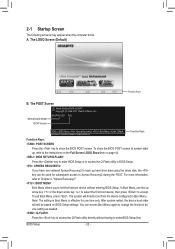
... access to accept. 2-1 Startup Screen The following screens may appear when the computer boots. The POST Screen Motherboard Model BIOS Version Award Modular BIOS v6.00PG Copyright (C) 1984-2011, Award Software, Inc. The system will still be used for one time only. For...to select the first boot device, then press to Xpress Recovery2 during the POST. The LOGO Screen (Default) Function Keys B. BIOS Setup - 32 - GA-970A-UD3 D3a . . . . : BIOS Setup : XpressRecovery2 : Boot Menu : Qflash 04/29/2011-RD970-SB950-7A66FG05C-00 Function Keys Function Keys: : POST SCREEN ...
... access to accept. 2-1 Startup Screen The following screens may appear when the computer boots. The POST Screen Motherboard Model BIOS Version Award Modular BIOS v6.00PG Copyright (C) 1984-2011, Award Software, Inc. The system will still be used for one time only. For...to select the first boot device, then press to Xpress Recovery2 during the POST. The LOGO Screen (Default) Function Keys B. BIOS Setup - 32 - GA-970A-UD3 D3a . . . . : BIOS Setup : XpressRecovery2 : Boot Menu : Qflash 04/29/2011-RD970-SB950-7A66FG05C-00 Function Keys Function Keys: : POST SCREEN ...

Manual
Page 33
...keys available for the current submenus Access the Q-Flash utility Display system information Save all the changes and exit the BIOS Setup program Save CMOS to BIOS Load CMOS from BIOS BIOS Setup Program Function Keys Move the selection bar to select an item Execute command or enter the submenu Main Menu:...item is in the Item Help block on the right side of the submenu. • If you do not find the settings you enter the BIOS Setup program, the Main Menu (as shown below) appears on the bottom line of a highlighted setup option is not stable as usual, select...
...keys available for the current submenus Access the Q-Flash utility Display system information Save all the changes and exit the BIOS Setup program Save CMOS to BIOS Load CMOS from BIOS BIOS Setup Program Function Keys Move the selection bar to select an item Execute command or enter the submenu Main Menu:...item is in the Item Help block on the right side of the submenu. • If you do not find the settings you enter the BIOS Setup program, the Main Menu (as shown below) appears on the bottom line of a highlighted setup option is not stable as usual, select...
Manual
Page 34
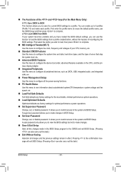
...Profile 1-8) and name each profile. First enter the profile name (to erase the default profile name, use this function to load the BIOS settings from BIOS If your CPU, memory, etc. Standard CMOS Features Use this menu to see information about autodetected system/CPU temperature, system ... F12: Load CMOS from a profile created before, without the hassles of errors that stop the system boot, etc. Advanced BIOS Features Use this menu to configure the device boot order, advanced features available on the CPU, and the primary display adapter. Integrated ...
...Profile 1-8) and name each profile. First enter the profile name (to erase the default profile name, use this function to load the BIOS settings from BIOS If your CPU, memory, etc. Standard CMOS Features Use this menu to see information about autodetected system/CPU temperature, system ... F12: Load CMOS from a profile created before, without the hassles of errors that stop the system boot, etc. Advanced BIOS Features Use this menu to configure the device boot order, advanced features available on the CPU, and the primary display adapter. Integrated ...
Manual
Page 35
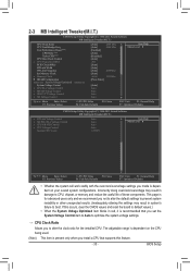
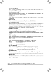
BIOS Setup Core Performance Boost (Note) CPB Ratio (Note) Turbo CPB (Note) CPU Host Clock Control x CPU Frequency(MHz) PCIE Clock(MHz) HT Link Width HT ...
BIOS Setup Core Performance Boost (Note) CPB Ratio (Note) Turbo CPB (Note) CPU Host Clock Control x CPU Frequency(MHz) PCIE Clock(MHz) HT Link Width HT ...
Manual
Page 36
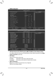
... The adjustable is dependent on the CPU being installed. (Note) This item is from 200 MHz to manually set the memory clock as required. BIOS Setup - 36 - CPU Frequency(MHz) Allows you install a CPU that the CPU frequency be configurable. HT Link Frequency Allows you alter the ...controller frequency for automated system reboot, or clear the CMOS values to reset the board to manually set the frequency for the CPB. Auto BIOS will automatically adjust the HT Link Frequency. (Default) x1~x10 Sets HT Link Frequency to 150 MHz. CPU NorthBridge Freq. Important It ...
... The adjustable is dependent on the CPU being installed. (Note) This item is from 200 MHz to manually set the memory clock as required. BIOS Setup - 36 - CPU Frequency(MHz) Allows you install a CPU that the CPU frequency be configurable. HT Link Frequency Allows you alter the ...controller frequency for automated system reboot, or clear the CMOS values to reset the board to manually set the frequency for the CPB. Auto BIOS will automatically adjust the HT Link Frequency. (Default) x1~x10 Sets HT Link Frequency to 150 MHz. CPU NorthBridge Freq. Important It ...
Manual
Page 37
... x Row Cycle Time x RAS to be configurable. DCTs Mode Allows you to single dual-channel. Ganged Sets memory control mode to set memory control mode. BIOS Setup Auto 10T 10T Auto 5T 5T Auto 33T 33T Auto 4T 4T DCT0 DCT1 Item Help Menu Level Move Enter: Select F5...
... x Row Cycle Time x RAS to be configurable. DCTs Mode Allows you to single dual-channel. Ganged Sets memory control mode to set memory control mode. BIOS Setup Auto 10T 10T Auto 5T 5T Auto 33T 33T Auto 4T 4T DCT0 DCT1 Item Help Menu Level Move Enter: Select F5...

Manual
Page 38
... : Auto (default), 8T~40T. Trfc1 for DIMM2, DIMM4 Options are : Auto (default), 4T~9T. Precharge Time Options are : Auto (default), 90ns, 110ns, 160ns, 300ns, 350ns. BIOS Setup - 38 - 1T/2T Command Timing Options are : Auto (default), 10T~56T. Row Cycle Time Options are : Auto (default), 1T, 2T. Data Drive Strength Options...
... : Auto (default), 8T~40T. Trfc1 for DIMM2, DIMM4 Options are : Auto (default), 4T~9T. Precharge Time Options are : Auto (default), 90ns, 110ns, 160ns, 300ns, 350ns. BIOS Setup - 38 - 1T/2T Command Timing Options are : Auto (default), 10T~56T. Row Cycle Time Options are : Auto (default), 1T, 2T. Data Drive Strength Options...


