Manual
Page 5
... 1-2 Feature Summary 12 1-3 Installation of the CPU and CPU Cooler 14 1-3-1 Installation of the CPU 14 1-3-2 Installation of the CPU Cooler 15 1-4 Installation of Memory 16 1-5 Installation of Expansion Cards 18 1-6 I/O Back Panel Introduction 19 1-7 Connectors Introduction 20 Chapter 2 BIOS Setup 31 The Main Menu (Example BIOS Ver.: GA-965P-DS3, F10a 32 2-1 Standard CMOS Features 34...
... 1-2 Feature Summary 12 1-3 Installation of the CPU and CPU Cooler 14 1-3-1 Installation of the CPU 14 1-3-2 Installation of the CPU Cooler 15 1-4 Installation of Memory 16 1-5 Installation of Expansion Cards 18 1-6 I/O Back Panel Introduction 19 1-7 Connectors Introduction 20 Chapter 2 BIOS Setup 31 The Main Menu (Example BIOS Ver.: GA-965P-DS3, F10a 32 2-1 Standard CMOS Features 34...
Manual
Page 9
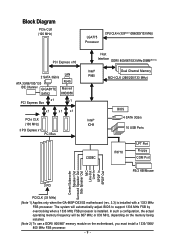
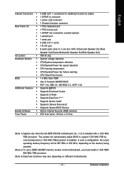
... a 1333/1066/ 800 MHz FSB processor. - 9 - Block Diagram PCIe CLK (100 MHz) LGA775 Processor CPU CLK+/-(333(Note 1)/266/200/133 MHz) PCI Express x16 2 SATA 3Gb/s LAN ATA 33/66/100/133 RJ45 IDE Channel GIGABYTE Marvell SATA2 88E8056 x1 PCI Express Bus x1 x1 x1 x1 PCIe CLK (100 MHz... Out Surround Speaker Out Side Speaker Out MIC Line-Out Line-In SPDIF In SPDIF Out 3 PCI PCICLK (33 MHz) (Note 1) Applies only when the GA-965P-DS3/S3 motherboard (rev. 3.3) is installed.
... a 1333/1066/ 800 MHz FSB processor. - 9 - Block Diagram PCIe CLK (100 MHz) LGA775 Processor CPU CLK+/-(333(Note 1)/266/200/133 MHz) PCI Express x16 2 SATA 3Gb/s LAN ATA 33/66/100/133 RJ45 IDE Channel GIGABYTE Marvell SATA2 88E8056 x1 PCI Express Bus x1 x1 x1 x1 PCIe CLK (100 MHz... Out Surround Speaker Out Side Speaker Out MIC Line-Out Line-In SPDIF In SPDIF Out 3 PCI PCICLK (33 MHz) (Note 1) Applies only when the GA-965P-DS3/S3 motherboard (rev. 3.3) is installed.
Manual
Page 11
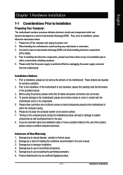
...the conditions recommended in the user manual. 3. Before using the product, please verify that the power supply is best to be an unofficial Gigabyte product. - 11 - Turning on top of an antistatic pad or within the computer casing. 6. Instances of the product, please consult ...not place the computer system on an uneven surface. 7. Product determined to wear an electrostatic discharge (ESD) cuff when handling electronic components (CPU, RAM). 4. Damage due to use exceeding the permitted parameters. 6. Damage due to use of electrostatic discharge (ESD). Prior to the...
...the conditions recommended in the user manual. 3. Before using the product, please verify that the power supply is best to be an unofficial Gigabyte product. - 11 - Turning on top of an antistatic pad or within the computer casing. 6. Instances of the product, please consult ...not place the computer system on an uneven surface. 7. Product determined to wear an electrostatic discharge (ESD) cuff when handling electronic components (CPU, RAM). 4. Damage due to use exceeding the permitted parameters. 6. Damage due to use of electrostatic discharge (ESD). Prior to the...
Manual
Page 12
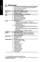
...; 6 SATA 3Gb/s connectors Š 1 CPU fan connector Š 1 system fan connector Š 1 power fan connector Š 1 northbridge fan connector Š 1 front panel connector Š 1 front audio connector Š 1 CD In connector "*" Only the GA-965P-DS3 adopts All-Solid Capacitor design. Supports RAID ..., allowing connection of 1 FDD device - 4 SATA 3Gb/s connectors (SATAII0,1, 2, 3), allowing connection of 4 SATA 3Gb/s devices Š Onboard GIGABYTE SATA2 chip - 1 IDE connector (UDMA 33/ATA 66/ATA 100/ATA 133), allowing connection of 2 IDE devices - 2 SATA 3Gb/s connectors ...
...; 6 SATA 3Gb/s connectors Š 1 CPU fan connector Š 1 system fan connector Š 1 power fan connector Š 1 northbridge fan connector Š 1 front panel connector Š 1 front audio connector Š 1 CD In connector "*" Only the GA-965P-DS3 adopts All-Solid Capacitor design. Supports RAID ..., allowing connection of 1 FDD device - 4 SATA 3Gb/s connectors (SATAII0,1, 2, 3), allowing connection of 4 SATA 3Gb/s devices Š Onboard GIGABYTE SATA2 chip - 1 IDE connector (UDMA 33/ATA 66/ATA 100/ATA 133), allowing connection of 2 IDE devices - 2 SATA 3Gb/s connectors ...
Manual
Page 13
... I/O Control Š IT8718 chip Hardware Monitor Š System voltage detection Š CPU/System temperature detection Š CPU/System/Power fan speed detection Š CPU warning temperature Š CPU/System/Power fan failure warning Š CPU Smart Fan Control BIOS Š 1 8 Mbit flash ROM Š Use of...138; Norton Internet Security (OEM revision) Form Factor Š ATX form factor; 30.5cm x 21.0cm (Note 1) Applies only when the GA-965P-DS3/S3 motherboard (rev. 3.3) is installed. The system will be 667 MHz or 833 MHz, depending on the memory being installed. (Note 2)...
... I/O Control Š IT8718 chip Hardware Monitor Š System voltage detection Š CPU/System temperature detection Š CPU/System/Power fan speed detection Š CPU warning temperature Š CPU/System/Power fan failure warning Š CPU Smart Fan Control BIOS Š 1 8 Mbit flash ROM Š Use of...138; Norton Internet Security (OEM revision) Form Factor Š ATX form factor; 30.5cm x 21.0cm (Note 1) Applies only when the GA-965P-DS3/S3 motherboard (rev. 3.3) is installed. The system will be 667 MHz or 833 MHz, depending on the memory being installed. (Note 2)...
Manual
Page 14
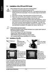
.... 5. Chipset: An Intel® Chipset that might cause damage to the upright position. Fig. 2 Remove the plastic covering on the CPU socket to the CPU during installation.) GA-965P-DS3/S3 Motherboard - 14 - Fig. 4 Once the CPU is not recommended that the motherboard supports the CPU. 2. Please make sure that the system bus frequency be set the...
.... 5. Chipset: An Intel® Chipset that might cause damage to the upright position. Fig. 2 Remove the plastic covering on the CPU socket to the CPU during installation.) GA-965P-DS3/S3 Motherboard - 14 - Fig. 4 Once the CPU is not recommended that the motherboard supports the CPU. 2. Please make sure that the system bus frequency be set the...
Manual
Page 15
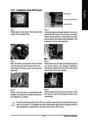
... header located on the motherboard.Pressing down the push pins diagonally. Fig. 6 Finally, please attach the power connector of the CPU cooler to the CPU cooler installation section of the user manual) Fig. 5 Please check the back of motherboard after installing. If the push pin is inserted as a ...of heat paste on the male push pin doesn't face inwards before installation. (This instruction is only for Intel boxed fan) Fig. 3 Place the CPU cooler atop the CPU and make sure the Male and Female push pin are joined closely. (for heat dissipation or using extreme care when removing the...
... header located on the motherboard.Pressing down the push pins diagonally. Fig. 6 Finally, please attach the power connector of the CPU cooler to the CPU cooler installation section of the user manual) Fig. 5 Please check the back of motherboard after installing. If the push pin is inserted as a ...of heat paste on the male push pin doesn't face inwards before installation. (This instruction is only for Intel boxed fan) Fig. 3 Place the CPU cooler atop the CPU and make sure the Male and Female push pin are joined closely. (for heat dissipation or using extreme care when removing the...
Manual
Page 21
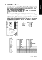
... power connector is able to all components and devices are properly installed. If a power supply is used (300W or greater). It is unable to the CPU. Pin No. Hardware Installation
... power connector is able to all components and devices are properly installed. If a power supply is used (300W or greater). It is unable to the CPU. Pin No. Hardware Installation
Manual
Page 22
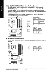
... fan cable to the CPU_FAN/SYS_FAN connector to prevent the CPU/system from overheating and failure. 1 CPU_FAN 1 CPU_FAN/SYS_FAN: Pin No. Definition 1 GND 2 +12V/Speed Control 3 Sense 4 Speed Control SYS_FAN 1 PWR_FAN PWR_FAN: Pin No. 1 2 3... will not work if you install it in the wrong direction and sometimes the chip fan will be damaged. 1 Pin No. Definition 1 GND 2 +12V 3 NC GA-965P-DS3/S3 Motherboard - 22 - A red power connector wire indicates a positive connection and requires a +12V power voltage. English 3/4/5) CPU_FAN / SYS_FAN / PWR_FAN (Cooler Fan Power ...
... fan cable to the CPU_FAN/SYS_FAN connector to prevent the CPU/system from overheating and failure. 1 CPU_FAN 1 CPU_FAN/SYS_FAN: Pin No. Definition 1 GND 2 +12V/Speed Control 3 Sense 4 Speed Control SYS_FAN 1 PWR_FAN PWR_FAN: Pin No. 1 2 3... will not work if you install it in the wrong direction and sometimes the chip fan will be damaged. 1 Pin No. Definition 1 GND 2 +12V 3 NC GA-965P-DS3/S3 Motherboard - 22 - A red power connector wire indicates a positive connection and requires a +12V power voltage. English 3/4/5) CPU_FAN / SYS_FAN / PWR_FAN (Cooler Fan Power ...
Manual
Page 33
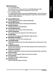
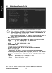
.... „ PC Health Status This setup page is the System auto detect Temperature, voltage, fan, speed. „ MB Intelligent Tweaker(M.I.T.) This setup page is control CPU clock and frequency ratio. „ Load Fail-Safe Defaults Fail-Safe Defaults indicates the value of the system parameters which the system would be in...
.... „ PC Health Status This setup page is the System auto detect Temperature, voltage, fan, speed. „ MB Intelligent Tweaker(M.I.T.) This setup page is control CPU clock and frequency ratio. „ Load Fail-Safe Defaults Fail-Safe Defaults indicates the value of the system parameters which the system would be in...
Manual
Page 35
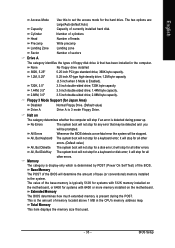
... prompted. Memory The category is display-only which is present during power up. The value of floppy disk drive A that has been installed in the CPU's memory address map. Whenever the BIOS detects a non-fatal error the system will determine the amount of currently installed hard disk. All, But Disk/Key...
... prompted. Memory The category is display-only which is present during power up. The value of floppy disk drive A that has been installed in the CPU's memory address map. Whenever the BIOS detects a non-fatal error the system will determine the amount of currently installed hard disk. All, But Disk/Key...
Manual
Page 36
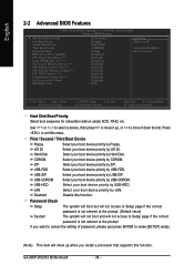
... if the correct password is not entered at the prompt. Press to 3 (Note) No-Execute Memory Protect (Note) CPU Enhanced Halt (C1E)(Note) CPU Thermal Monitor 2(TM2) (Note) CPU EIST Function (Note) Virtualization Technology(Note) Full Screen LOGO Show Init Display First [Press Enter] [Floppy] [Hard Disk...(or add-on cards) SCSI, RAID, etc. USB-HDD Select your boot device priority by USB-HDD. Disabled Disable this menu. GA-965P-DS3/S3 Motherboard - 36 - English 2-2 Advanced BIOS Features CMOS Setup Utility-Copyright (C) 1984-2006 Award Software Advanced BIOS Features Hard Disk ...
... if the correct password is not entered at the prompt. Press to 3 (Note) No-Execute Memory Protect (Note) CPU Enhanced Halt (C1E)(Note) CPU Thermal Monitor 2(TM2) (Note) CPU EIST Function (Note) Virtualization Technology(Note) Full Screen LOGO Show Init Display First [Press Enter] [Floppy] [Hard Disk...(or add-on cards) SCSI, RAID, etc. USB-HDD Select your boot device priority by USB-HDD. Disabled Disable this menu. GA-965P-DS3/S3 Motherboard - 36 - English 2-2 Advanced BIOS Features CMOS Setup Utility-Copyright (C) 1984-2006 Award Software Advanced BIOS Features Hard Disk ...
Manual
Page 37
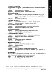
... 3 (Note) Enabled Disabled Limit CPUID Maximum value to PCI Express VGA card. CPU Thermal Monitor 2 (TM2) (Note) Enabled Disabled Enable CPU Thermal Monitor 2 (TM2) function. (Default value) Disable CPU Thermal Monitor 2 (TM2) function. Capability This feature allows your hard disk to ... that this function. - 37 - Disable CPUID Limit for operating system with multi processors mode supported. (Default Disabled value) Disable CPU Hyper Threading. Full Screen LOGO Show Enabled Disabled Show full screen logo at system startup. (Default value) Disable this function. PCI...
... 3 (Note) Enabled Disabled Limit CPUID Maximum value to PCI Express VGA card. CPU Thermal Monitor 2 (TM2) (Note) Enabled Disabled Enable CPU Thermal Monitor 2 (TM2) function. (Default value) Disable CPU Thermal Monitor 2 (TM2) function. Capability This feature allows your hard disk to ... that this function. - 37 - Disable CPUID Limit for operating system with multi processors mode supported. (Default Disabled value) Disable CPU Hyper Threading. Full Screen LOGO Show Enabled Disabled Show full screen logo at system startup. (Default value) Disable this function. PCI...
Manual
Page 44
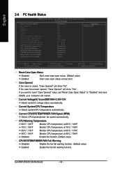
... 60oC / 140oF. 70oC / 158oF 80oC / 176oF 90oC / 194oF Monitor CPU temperature at next boot. Disabled Disable this function. (Default value) CPU/SYSTEM/POWER FAN Fail Warning Disabled Enabled Disable the fan fail warning function. (Default value) Enable the fan fail warning function. GA-965P-DS3/S3 Motherboard - 44 - Case Opened If the case is closed...
... 60oC / 140oF. 70oC / 158oF 80oC / 176oF 90oC / 194oF Monitor CPU temperature at next boot. Disabled Disable this function. (Default value) CPU/SYSTEM/POWER FAN Fail Warning Disabled Enabled Disable the fan fail warning function. (Default value) Enable the fan fail warning function. GA-965P-DS3/S3 Motherboard - 44 - Case Opened If the case is closed...
Manual
Page 45
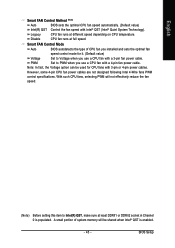
...PWM Set to Voltage when you installed and sets the optimal fan speed control mode for CPU fans with a 3-pin fan power cable. English Smart FAN Control Method (Note) Auto BIOS sets the optimal CPU fan speed automatically. (Default value) Intel(R) QST Control the fan speed with a 4-...pin fan power cable. A small portion of CPU fan you use a CPU fan with Intel® QST (Intel® Quiet System Technology). Disable CPU fan runs at least DDRII1 or DDRII2 socket in Channel 0 is enabled. - 45 - Note: In fact,...
...PWM Set to Voltage when you installed and sets the optimal fan speed control mode for CPU fans with a 3-pin fan power cable. English Smart FAN Control Method (Note) Auto BIOS sets the optimal CPU fan speed automatically. (Default value) Intel(R) QST Control the fan speed with a 4-...pin fan power cable. A small portion of CPU fan you use a CPU fan with Intel® QST (Intel® Quiet System Technology). Disable CPU fan runs at least DDRII1 or DDRII2 socket in Channel 0 is enabled. - 45 - Note: In fact,...
Manual
Page 46
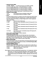
...items are for automatic system restart or clear the CMOS setup data and perform a safe restart. The option will automatically assign by CPU detection. CPU Host Clock Control Please note that the M.I .A. 2 System Memory Multiplier (SPD) Memory Frequency (Mhz) 533 High Speed DRAM ... show up when you set "System Voltage Control" to "Auto" to optimize the system voltage settings. GA-965P-DS3/S3 Motherboard - 46 - Doing a overclock or overvoltage on CPU, chipsets and memory modules may result in damages or shortened life expectancy to get higher performance. Robust Graphics...
...items are for automatic system restart or clear the CMOS setup data and perform a safe restart. The option will automatically assign by CPU detection. CPU Host Clock Control Please note that the M.I .A. 2 System Memory Multiplier (SPD) Memory Frequency (Mhz) 533 High Speed DRAM ... show up when you set "System Voltage Control" to "Auto" to optimize the system voltage settings. GA-965P-DS3/S3 Motherboard - 46 - Doing a overclock or overvoltage on CPU, chipsets and memory modules may result in damages or shortened life expectancy to get higher performance. Robust Graphics...
Manual
Page 47
... Timing Configuration 1. (Default value) Option 2 DRAM Timing Configuration 2. (Note 2) Applies only when the GA-965P-DS3/S3 motherboard (rev. 3.3) is installed. BIOS Setup Turbo Set C.I .A.2 to help make your system becomes unstable after you use a 1066 MHz FSB processor, set "CPU Host Frequency" to overcome wrong frequency issue. If your system more stable. Full...
... Timing Configuration 1. (Default value) Option 2 DRAM Timing Configuration 2. (Note 2) Applies only when the GA-965P-DS3/S3 motherboard (rev. 3.3) is installed. BIOS Setup Turbo Set C.I .A.2 to help make your system becomes unstable after you use a 1066 MHz FSB processor, set "CPU Host Frequency" to overcome wrong frequency issue. If your system more stable. Full...
Manual
Page 48
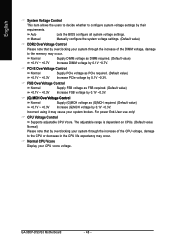
... Normal Supply PCIe voltage as PCIe required. (Default value) +0.1V ~ +0.3V Increase PCIe voltage by 0.1V ~0.7V. CPU Voltage Control Supports adjustable CPU Vcore. GA-965P-DS3/S3 Motherboard - 48 - Incorrect using it may occur. Auto Lets the BIOS configure all system voltage settings. Normal Supply DIMM...on CPUs. (Default value: Normal) Please note that by overclocking your system through the increase of the CPU voltage, damage to the CPU or decrease in the CPU life expectancy may occur. For power End-User use only! FSB OverVoltage Control Normal +0.1V ~ +0.3V...
... Normal Supply PCIe voltage as PCIe required. (Default value) +0.1V ~ +0.3V Increase PCIe voltage by 0.1V ~0.7V. CPU Voltage Control Supports adjustable CPU Vcore. GA-965P-DS3/S3 Motherboard - 48 - Incorrect using it may occur. Auto Lets the BIOS configure all system voltage settings. Normal Supply DIMM...on CPUs. (Default value: Normal) Please note that by overclocking your system through the increase of the CPU voltage, damage to the CPU or decrease in the CPU life expectancy may occur. For power End-User use only! FSB OverVoltage Control Normal +0.1V ~ +0.3V...
Manual
Page 57
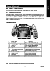
...to GIGABYTE website 10. C.I.A./C.I.A.2 and M.I.B./M.I.B.2 Enters the C.I.A./2 and M.I .B. GO Confirmation and Execution button 6. Function display LEDs Shows the current functions status 9. for special enhancement for CPU and Memory, 3) Smart-Fan control for managing fan speed control of CPU ...4. Help button Display EasyTuneTM 5 Help file 11. "Easy Mode" & "Advance Mode" Toggles between Easy and Advance Mode 7. GIGABYTE Logo Log on different motherboards. - 57 - Overclocking Enters the Overclocking setting page 2. English Chapter 4 Appendix 4-1 Unique Software Utilities...
...to GIGABYTE website 10. C.I.A./C.I.A.2 and M.I.B./M.I.B.2 Enters the C.I.A./2 and M.I .B. GO Confirmation and Execution button 6. Function display LEDs Shows the current functions status 9. for special enhancement for CPU and Memory, 3) Smart-Fan control for managing fan speed control of CPU ...4. Help button Display EasyTuneTM 5 Help file 11. "Easy Mode" & "Advance Mode" Toggles between Easy and Advance Mode 7. GIGABYTE Logo Log on different motherboards. - 57 - Overclocking Enters the Overclocking setting page 2. English Chapter 4 Appendix 4-1 Unique Software Utilities...
Manual
Page 66
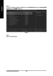
...from Windows installation CD-ROM disk, set First Boot Device under the Advanced BIOS Features menu to 3 No-Execute Memory Protect CPU Enhanced Halt (C1E) CPU Thermal Monitor 2(TM2) CPU EIST Function Virtualization Technology Full Screen LOGO Show Init Display First [Press Enter] [CDROM] [Hard Disk] [CDROM] [...BIOS Setup. +/-/PU/PD: Value F10: Save F6: Fail-Safe Defaults Figure 2 ESC: Exit F1: General Help F7: Optimized Defaults GA-965P-DS3/S3 Motherboard - 66 - CMOS Setup Utility-Copyright (C) 1984-2006 Award Software Advanced BIOS Features Hard Disk Boot Priority First Boot Device ...
...from Windows installation CD-ROM disk, set First Boot Device under the Advanced BIOS Features menu to 3 No-Execute Memory Protect CPU Enhanced Halt (C1E) CPU Thermal Monitor 2(TM2) CPU EIST Function Virtualization Technology Full Screen LOGO Show Init Display First [Press Enter] [CDROM] [Hard Disk] [CDROM] [...BIOS Setup. +/-/PU/PD: Value F10: Save F6: Fail-Safe Defaults Figure 2 ESC: Exit F1: General Help F7: Optimized Defaults GA-965P-DS3/S3 Motherboard - 66 - CMOS Setup Utility-Copyright (C) 1984-2006 Award Software Advanced BIOS Features Hard Disk Boot Priority First Boot Device ...


