Manual
Page 1
GA-965GM-DS2 (rev. 2.0) Intel® CoreTM 2 Extreme quad-core / CoreTM 2 Quad / Intel® CoreTM 2 Extreme dual-core / CoreTM 2 Duo / Intel® Pentium® Processor Extreme Edition / Intel® Pentium® D / Pentium® 4 LGA775 Processor Motherboard User's Manual Rev. 2002 12ME-965GMDR-2002R * The WEEE marking on the product indicates this product must not be disposed...
GA-965GM-DS2 (rev. 2.0) Intel® CoreTM 2 Extreme quad-core / CoreTM 2 Quad / Intel® CoreTM 2 Extreme dual-core / CoreTM 2 Duo / Intel® Pentium® Processor Extreme Edition / Intel® Pentium® D / Pentium® 4 LGA775 Processor Motherboard User's Manual Rev. 2002 12ME-965GMDR-2002R * The WEEE marking on the product indicates this product must not be disposed...
Manual
Page 2
Motherboard GA-965GM-DS2 (rev. 2.0) Oct. 1, 2006 Motherboard GA-965GM-DS2 (rev. 2.0) Oct. 1, 2006
Motherboard GA-965GM-DS2 (rev. 2.0) Oct. 1, 2006 Motherboard GA-965GM-DS2 (rev. 2.0) Oct. 1, 2006
Manual
Page 4
Table of Contents ItemChecklist ...6 OptionalAccessories ...6 GA-965GM-DS2 (rev. 2.0) Motherboard Layout 7 Block Diagram ...8 Chapter 1 Hardware Installation 9 1-1 Considerations Prior to Installation 9 1-2 Feature Summary 10 1-3 Installation of the CPU and CPU Cooler 12 1-3-1 Installation of the ...
Table of Contents ItemChecklist ...6 OptionalAccessories ...6 GA-965GM-DS2 (rev. 2.0) Motherboard Layout 7 Block Diagram ...8 Chapter 1 Hardware Installation 9 1-1 Considerations Prior to Installation 9 1-2 Feature Summary 10 1-3 Installation of the CPU and CPU Cooler 12 1-3-1 Installation of the ...
Manual
Page 7
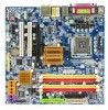
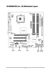
GA-965GM-DS2 (rev. 2.0) Motherboard Layout KB_MS ATX_12V LGA775 CPU_FAN ATX GA-965GM-DS2 FDD IT8718 COMA LPT VGA USB_1394 USB_LAN Intel® G965 AUDIO F_AUDIO Marvell 88E8056 PCIE_16 PCI1 BIOS PCI2 Intel® ICH8 IDE GIGABYTE SATA2 CD_IN CODEC REV: 2.0 PCIE_1 CI CLR_CMOS BATTERY COMB F1_1394 F2_1394 F_USB2 F_USB3 SATAII2 SATAII3 SPDIF_IO SYS _FAN F_USB1 SATAII0 GSATAII0 SATAII1 GSATAII1 DDRII1 DDRII2 DDRII3 DDRII4 PWR_LED F_PANEL - 7 -
GA-965GM-DS2 (rev. 2.0) Motherboard Layout KB_MS ATX_12V LGA775 CPU_FAN ATX GA-965GM-DS2 FDD IT8718 COMA LPT VGA USB_1394 USB_LAN Intel® G965 AUDIO F_AUDIO Marvell 88E8056 PCIE_16 PCI1 BIOS PCI2 Intel® ICH8 IDE GIGABYTE SATA2 CD_IN CODEC REV: 2.0 PCIE_1 CI CLR_CMOS BATTERY COMB F1_1394 F2_1394 F_USB2 F_USB3 SATAII2 SATAII3 SPDIF_IO SYS _FAN F_USB1 SATAII0 GSATAII0 SATAII1 GSATAII1 DDRII1 DDRII2 DDRII3 DDRII4 PWR_LED F_PANEL - 7 -
Manual
Page 10
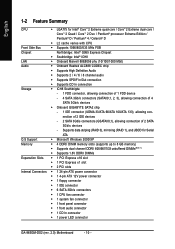
... (SATAII0,1, 2, 3), allowing connection of 2 SATA 3Gb/s devices - nection of 2 IDE devices - 2 SATA 3Gb/s connectors (GSATAII0,1), allowing connection of 4 SATA 3Gb/s devices Š Onboard GIGABYTE SATA2 chip - 1 IDE connector (UDMA 33/ATA 66/ATA 100/ATA 133), allowing con- English 1-2 Feature Summary CPU Š LGA775 for Serial ATA O.S Support Š...Š 1 CPU fan connector Š 1 system fan connector Š 1 front panel connector Š 1 front audio connector Š 1 CD In connector Š 1 power LED connector GA-965GM-DS2 (rev. 2.0) Motherboard - 10 -
... (SATAII0,1, 2, 3), allowing connection of 2 SATA 3Gb/s devices - nection of 2 IDE devices - 2 SATA 3Gb/s connectors (GSATAII0,1), allowing connection of 4 SATA 3Gb/s devices Š Onboard GIGABYTE SATA2 chip - 1 IDE connector (UDMA 33/ATA 66/ATA 100/ATA 133), allowing con- English 1-2 Feature Summary CPU Š LGA775 for Serial ATA O.S Support Š...Š 1 CPU fan connector Š 1 system fan connector Š 1 front panel connector Š 1 front audio connector Š 1 CD In connector Š 1 power LED connector GA-965GM-DS2 (rev. 2.0) Motherboard - 10 -
Manual
Page 12
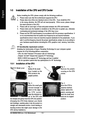
... socket. Fig. 3 Notice the small gold colored triangle located on the CPU prior to the upright position. If you wish to the CPU during installation.) GA-965GM-DS2 (rev. 2.0) Motherboard - 12 - Align the indented corner of heat sink paste between your thumb and forefinger, carefully place it into its original position. Please add an...
... socket. Fig. 3 Notice the small gold colored triangle located on the CPU prior to the upright position. If you wish to the CPU during installation.) GA-965GM-DS2 (rev. 2.0) Motherboard - 12 - Align the indented corner of heat sink paste between your thumb and forefinger, carefully place it into its original position. Please add an...
Manual
Page 14
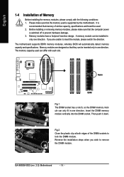
..., please switch the direction. Memory modules have a foolproof insertion design. The motherboard supports DDRII memory modules, whereby BIOS will automatically detect memory capacity and specifications. GA-965GM-DS2 (rev. 2.0) Motherboard - 14 - Notch DDRII Fig.1 The DIMM socket has a notch, so the DIMM memory module can be installed in one direction. Fig.2 Close the plastic...
..., please switch the direction. Memory modules have a foolproof insertion design. The motherboard supports DDRII memory modules, whereby BIOS will automatically detect memory capacity and specifications. GA-965GM-DS2 (rev. 2.0) Motherboard - 14 - Notch DDRII Fig.1 The DIMM socket has a notch, so the DIMM memory module can be installed in one direction. Fig.2 Close the plastic...
Manual
Page 16
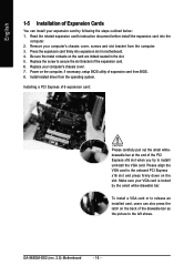
... a VGA card or to the left shows. Read the related expansion card's instruction document before install the expansion card into expansion slot in the slot. 5. GA-965GM-DS2 (rev. 2.0) Motherboard - 16 - English 1-5 Installation of Expansion Cards You can also press the latch on the card are indeed seated in motherboard. 4. Make sure your expansion...
... a VGA card or to the left shows. Read the related expansion card's instruction document before install the expansion card into expansion slot in the slot. 5. GA-965GM-DS2 (rev. 2.0) Motherboard - 16 - English 1-5 Installation of Expansion Cards You can also press the latch on the card are indeed seated in motherboard. 4. Make sure your expansion...
Manual
Page 18
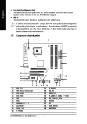
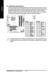
... 15 19 14 78 11) F_AUDIO 12) CD_IN 13) SPDIF_IO 14) F_USB1 / F_USB2 / F_USB3 15) F1_1394 / F2_1394 16) COMB 17) CI 18) CLR_CMOS 19) BATTERY GA-965GM-DS2 (rev. 2.0) Motherboard - 18 - Microphone must be reconfigured to the default Mic In jack ( ). Please refer to the 2-/4-/6-/8- MIC In The default MIC In jack. English Line...
... 15 19 14 78 11) F_AUDIO 12) CD_IN 13) SPDIF_IO 14) F_USB1 / F_USB2 / F_USB3 15) F1_1394 / F2_1394 16) COMB 17) CI 18) CLR_CMOS 19) BATTERY GA-965GM-DS2 (rev. 2.0) Motherboard - 18 - Microphone must be reconfigured to the default Mic In jack ( ). Please refer to the 2-/4-/6-/8- MIC In The default MIC In jack. English Line...
Manual
Page 20
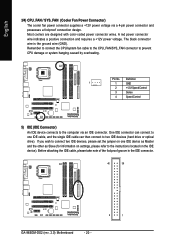
Pin No. Before attaching the IDE cable, please take note of the foolproof groove in the IDE connector. 40 39 GA-965GM-DS2 (rev. 2.0) Motherboard - 20 - 2 1 A red power connector wire indicates a positive connection and requires a +12V power voltage. Definition 1 1 GND 2 +12V/Speed Control 3 Sense 4 Speed Control 5) IDE (IDE Connector) ...
Pin No. Before attaching the IDE cable, please take note of the foolproof groove in the IDE connector. 40 39 GA-965GM-DS2 (rev. 2.0) Motherboard - 20 - 2 1 A red power connector wire indicates a positive connection and requires a +12V power voltage. Definition 1 1 GND 2 +12V/Speed Control 3 Sense 4 Speed Control 5) IDE (IDE Connector) ...
Manual
Page 22
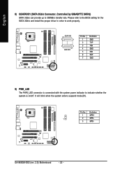
English 8) GSATAII0/1 (SATA 3Gb/s Connector, Controlled by GIGABYTE SATA2) SATA 3Gb/s can provide up to indicate whether the system is on/off. GA-965GM-DS2 (rev. 2.0) Motherboard - 22 - GSATAII0 7 1 1 7 GSATAII1 Pin No. 1 2 3 4 5 6 7 Definition GND TXP TXN GND RXN RXP GND 9) PWR_LED The PWR_LED connector is connected with the system power indicator ...
English 8) GSATAII0/1 (SATA 3Gb/s Connector, Controlled by GIGABYTE SATA2) SATA 3Gb/s can provide up to indicate whether the system is on/off. GA-965GM-DS2 (rev. 2.0) Motherboard - 22 - GSATAII0 7 1 1 7 GSATAII1 Pin No. 1 2 3 4 5 6 7 Definition GND TXP TXN GND RXN RXP GND 9) PWR_LED The PWR_LED connector is connected with the system power indicator ...
Manual
Page 24
... assignments carefully while you wish to use the front audio function, connect the front panel audio module to this connector, please refer to this connector. GA-965GM-DS2 (rev. 2.0) Motherboard - 24 - If you connect the front panel audio module.
... assignments carefully while you wish to use the front audio function, connect the front panel audio module to this connector, please refer to this connector. GA-965GM-DS2 (rev. 2.0) Motherboard - 24 - If you connect the front panel audio module.
Manual
Page 26
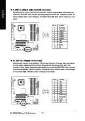
... optional front USB cable, please contact your local dealer. 9 1 10 2 Pin No. 1 2 3 4 5 6 7 8 9 10 Definition TPA+ TPAGND GND TPB+ TPBPower (12V) Power (12V) No Pin GND GA-965GM-DS2 (rev. 2.0) Motherboard - 26 - Be careful with the polarity of the front USB connector. For optional IEEE 1394 cable, please contact your local dealer. 9 1 10 2 Pin No...
... optional front USB cable, please contact your local dealer. 9 1 10 2 Pin No. 1 2 3 4 5 6 7 8 9 10 Definition TPA+ TPAGND GND TPB+ TPBPower (12V) Power (12V) No Pin GND GA-965GM-DS2 (rev. 2.0) Motherboard - 26 - Be careful with the polarity of the front USB connector. For optional IEEE 1394 cable, please contact your local dealer. 9 1 10 2 Pin No...
Manual
Page 28
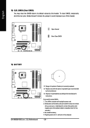
... in the battery holder to connect the positive and negative pins in and turn on the computer. - 28 - Open: Normal Short: Clear CMOS 19) BATTERY GA-965GM-DS2 (rev. 2.0) Motherboard Danger of this header.
... in the battery holder to connect the positive and negative pins in and turn on the computer. - 28 - Open: Normal Short: Clear CMOS 19) BATTERY GA-965GM-DS2 (rev. 2.0) Motherboard Danger of this header.
Manual
Page 30
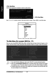
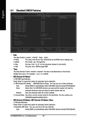
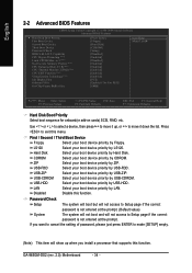
English : Boot Menu Select boot sequence for stability. 3. This action makes the system reset to access advanced options. 2. GA-965GM-DS2 (rev. 2.0) Motherboard - 30 - Boot Menu == Select a Boot First device == Floppy LS120 Hard Disk CDROM ZIP USB-FDD USB-ZIP USB-CDROM USB-HDD... (as usual. Intel G965 BIOS for your motherboard. Press to exit this chapter are for reference only and may differ from the exact settings for 965GM-DS2 F1 . . . . :BIOS Setup/Q-Flash, : Xpress Recovery2, : Boot Menu 10/12/2006-G965-ICH8-6A79LG0PC-00 : Boot Menu Use < > or < > to select a ...
English : Boot Menu Select boot sequence for stability. 3. This action makes the system reset to access advanced options. 2. GA-965GM-DS2 (rev. 2.0) Motherboard - 30 - Boot Menu == Select a Boot First device == Floppy LS120 Hard Disk CDROM ZIP USB-FDD USB-ZIP USB-CDROM USB-HDD... (as usual. Intel G965 BIOS for your motherboard. Press to exit this chapter are for reference only and may differ from the exact settings for 965GM-DS2 F1 . . . . :BIOS Setup/Q-Flash, : Xpress Recovery2, : Boot Menu 10/12/2006-G965-ICH8-6A79LG0PC-00 : Boot Menu Use < > or < > to select a ...
Manual
Page 32
...:Auto) IDE Channel 2/3 Master, IDE Channel 4/5 Master, Slave IDE Auto-Detection Press "Enter" to select this to automatically detect IDE/SATA devices during POST(default) GA-965GM-DS2 (rev. 2.0) Motherboard - 32 - You can manually input the correct settings Access Mode Use this option for automatic device detection. You can use one of the two...
...:Auto) IDE Channel 2/3 Master, IDE Channel 4/5 Master, Slave IDE Auto-Detection Press "Enter" to select this to automatically detect IDE/SATA devices during POST(default) GA-965GM-DS2 (rev. 2.0) Motherboard - 32 - You can manually input the correct settings Access Mode Use this option for automatic device detection. You can use one of the two...
Manual
Page 34
...-ZIP Select your boot device priority by USB-ZIP. If you install a processor that supports this function. CDROM Select your boot device priority by CDROM. GA-965GM-DS2 (rev. 2.0) Motherboard - 34 - USB-CDROM Select your boot device priority by USB-CDROM. Capability CPU Hyper-Threading (Note) Limit CPUID Max. USB-FDD Select your boot...
...-ZIP Select your boot device priority by USB-ZIP. If you install a processor that supports this function. CDROM Select your boot device priority by CDROM. GA-965GM-DS2 (rev. 2.0) Motherboard - 34 - USB-CDROM Select your boot device priority by USB-CDROM. Capability CPU Hyper-Threading (Note) Limit CPUID Max. USB-FDD Select your boot...
Manual
Page 36
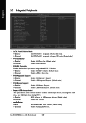
...~3 to detect USB storage devices, including USB flash drives and USB hard drives during POST. Enabled Enable USB 2.0 Controller. (Default value) Disabled Disable USB 2.0 Controller. GA-965GM-DS2 (rev. 2.0) Motherboard - 36 -
...~3 to detect USB storage devices, including USB flash drives and USB hard drives during POST. Enabled Enable USB 2.0 Controller. (Default value) Disabled Disable USB 2.0 Controller. GA-965GM-DS2 (rev. 2.0) Motherboard - 36 -
Manual
Page 38
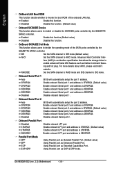
...Port Disabled 378/IRQ7 278/IRQ5 3BC/IRQ7 Disable onboard LPT port. GA-965GM-DS2 (rev. 2.0) Motherboard - 38 - OnBoard SATA/IDE Ctrl Mode This function allows users to invoke the boot ROM of the SATA ports controlled by the GIGABYTE SATA2 controller. Enable onboard LPT port and address is 378/IRQ7. .... RAID/IDE Set the SATA channel to RAID mode and IDE channel to enable or disable the SATA/IDE ports controlled by the GIGABYTE SATA2 controller. Using Parallel port as Native Command Queu- Disable onboard Serial port 2. ing and hot plug. Enabled Enable this function.(Default...
...Port Disabled 378/IRQ7 278/IRQ5 3BC/IRQ7 Disable onboard LPT port. GA-965GM-DS2 (rev. 2.0) Motherboard - 38 - OnBoard SATA/IDE Ctrl Mode This function allows users to invoke the boot ROM of the SATA ports controlled by the GIGABYTE SATA2 controller. Enable onboard LPT port and address is 378/IRQ7. .... RAID/IDE Set the SATA channel to RAID mode and IDE channel to enable or disable the SATA/IDE ports controlled by the GIGABYTE SATA2 controller. Using Parallel port as Native Command Queu- Disable onboard Serial port 2. ing and hot plug. Enabled Enable this function.(Default...
Manual
Page 40
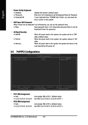
Auto assign IRQ to PCI 2. (Default value) Set IRQ 3,4,5,7,9,10,11,12,14,15 to power on the system. GA-965GM-DS2 (rev. 2.0) Motherboard - 40 - Enter Input password (from 1 to 5 characters to set the Keyboard Power On Password. AC Back Function Soft-Off When AC-power back to ...
Auto assign IRQ to PCI 2. (Default value) Set IRQ 3,4,5,7,9,10,11,12,14,15 to power on the system. GA-965GM-DS2 (rev. 2.0) Motherboard - 40 - Enter Input password (from 1 to 5 characters to set the Keyboard Power On Password. AC Back Function Soft-Off When AC-power back to ...


